
• The move to the new server is done. There are some software and database maintenance updates in process. This has us passing the hat around to help out. We appreciate any donations. Seriously, even a dollar helps. The payment page may be found here - https://www.audiokarma.org/support.html

SX-737 tuner AWE-043

pa_200

Well-Known Member
Hi Pioneer Friends,

I got a working SX-737 still with original parts. It’s still running with the old parts and I plan a major recap and transistor replacement on all boards, except the tuner board AWE-043.

That board seems a bit tricky according to Larrys post here
https://audiokarma.org/forums/index.php?threads/pioneer-sx-737.760111/#post-10349650

He doesn’t recommend to touch the small caps “but the caps that are LESS than 1 microfarad should be left alone as a few could disturb the tuner's adjustments. TALK to me if / before doing the tuner - there are pitfalls!!"

But what about the 5 cssa type caps C38, C39, C40, C49 and C50. And the same with the trouble maker 2SC725 Q8, Q9 ?

I don’t want to disturb the tuner adjustment, so what’s your experience and advice with that tuner board?
 
Register to hide this ad
C38 - Replace, interstage pass-through after HA1156 preamp of input and before quadrature detection;
C39 - Replace, Same as C38;
C40 - Replace, interstage pass-through after Stereo lock detection;
C49 - Replace, isolation of audio output from decoder, L channel;
C50 - Replace, isolation of audio output from decoder, R channel;
Q8, Q9 - Replace both, audio output only, so no effect on reception.
 
Sounds good, will replace all caps with film type, and Q8-Q9 with KSA992.
Anything else that needs attention on that tuner board? Like C28, C66….Q10-11...
 
hi pa_200
I hope you'll post back with whatever you decide to do and how it works out in your tuner.
 
Sure, will do and give a brief feedback afterwards. Have to wait for some other things first. This SX-737 project will start by mid-November.
 
My tuner worked before I started the rebuild with the power supply, protection board and the rest. But after finishing all the other boards, with the first test on DBT, the tuner stays totally dead. The AWE-043 has not been touched.

No movement at all when powering up is seen from Signal or Tuner indicator and while moving the dialing wheel. Pin 20 and 3 have 13,3vdc but nothing happens.
Nothing, not even a faint signal can be heard. The only move is the function light indicating the switch from AUX or Phono to FM.

Would prefer to find the issue before continuing on the tuner assay with changing the cssa type caps C38, C39, C40, C49, C50 and the two transistors 2SC725 Q8, Q9.

Every help is highly appreciated where to look next.

If you want info what has been done before on the other boards, that is the second thread.

https://audiokarma.org/forums/index...roblem-with-short-circuit-help-needed.978277/
 
The voltage of HA1156 as a start
1 = 13,28 all vdc
2 = 2,99
3 = 4,74
4 = 11,55
5 = 11,55
6 = 13,36
7 = 0,0
8 = 2,50
9 = 2,51
10 = 1,73
11 = 2,51
12 = 2,51
13 = 2,51
14 = 3,15
 
If you have no fm signal meter action with a strong antenna signal your problem is not with the stereo decoder ha1156. I am on my phone so I need access to my computer to look at the schematic to recall what they used for a fm detector, and IF filter chain to verify that those are working properly, that is where you should be looking. does it use the ha1137 if system chip?
Does the fm front end and IF filter chain get the proper supply V?
 
If pin 3 is the supply for the frontend, then we have 13,3vdc there, like in the SM.
The tuner board has 3 chips on it, HA1156, HA1137 and HA1138

The voltage of HA1137 are as follows
1 = 2,47 all vdc
2 = 2,47
3 = 2,47
4 = 0,0
5 = 0,0
6 = 0,0
7 = 1,42
8 = 1,42
9 = 1,42
10 = 1,42
11 = 13,22
12 = 0,0
13 = 0,0
14 = 0,0
15 = 0,0
16 = 0,0

If the HA1137 chip controls AM reception, that isn’t needed. I don’t use AM Station. But If HA1137 is needed for proper function, will give you the voltage as well.
 
Last edited:
Right off the hat I can see you have issues with the Hitachi HA1137, the reference bias pin 10 must be ~5.6V
You are needing to understand how the tuner works and the signal flow.
HA1137 is the FM IF system chip.
You have no supply V to the HA1137 it comes in on terminal 4 and goes to pin2 on HA1137 (Q5) :) how about switch to FM mode to start with, if you are still not getting ~13V on HA1137-pin 2 then check the function switch nd its wiring because that is the source of your problem not the tuner.
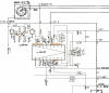
This voltage is switched to keep the noise down from the IF system when in AM mode
You can read other receiver manuals that use the HA1137, some of them usually provide more theory on how it works
Too many times I read that things were working okay before someone laid there hands on them . They usually do not disclose everything that lead up to the the malfunction and then expect the experts to figure it out what is wrong and not knowing the whole story. :) Fun wow
 
Thanks for your help. I like it step be step and will post every information necessary.
All voltage from tuner assy AWE-043

Function switch to FM, PIN 3 = 13,05 vdc and PIN 4 = 1,58 vdc, Q5 (HA1137) PIN2 = 2,49 vdc
But if I switch to AM, then PIN 3 = 0,0 vdc and PIN 4 = 13,21 vdc, Q5 (HA1137) PIN2 = 2,86 vdc

You expected ~13V on HA1137-pin 2, but my service manual page 31 shows in red 1,5V for PIN 1 – 2 – 3.
 
Last edited:
The front end is dual FET, with a BJT interstage, and two ceramic filters (probably MuRata 10.7s) with a BJT amplifier between them. The band-pass signal from the second ceramic filter feeds a Hitachi HA1137 input at Pin 1 on the IC.

The HA1137 gets its Vcc (supply) at Pin 11 on the IC, up to 14V. It may be helpful to measure the voltage present in FM mode.

The factory schematics show the unit with voltage measurements, but bear in mind that the schematics also show the position of the function switch (S1) in the legend with an underline. On my diagrams, the switch is shown in the AM position, so the circuit voltages may not be correct for FM mode.

upload_2021-12-17_15-9-5.png


Function switch to FM, PIN 3 = 13,05 vdc and PIN 4 = 1,58 vdc, Q5 (HA1137) PIN2 = 2,49 vdc
But if I switch to AM, then PIN 3 = 0,0 vdc and PIN 4 = 13,21 vdc, Q5 (HA1137) PIN2 = 2,86 vdc

I believe that is correct. Function switch S1 supplies +13.5V to the AWE-043 board Pin 3 when FM is selected, and supplies +13.5V to Pin 4 whenever FM is NOT selected to null out any FM signal at the HA1137.
 
Last edited:
Since we have already established that the HA1156 is receiving +13.5V (post #9) we can presume that it should be active and ready to process signals from the HA1137. It just needs to receive that signal from Pin 6 on the HA1137 IC.

Do you have a signal tracer available?
 
If the HA1137 chip controls AM reception, that isn’t needed. I don’t use AM Station. But If HA1137 is needed for proper function, will give you the voltage as well.

The HA1138 is the AM radio demodulator/detector.

The FM section uses the HA1137 as the detector and the HA1156 as the stereo decoder. The HA1137 sends a composite audio signal to the HA1137 to be decoded into two separate channels.
 
Thank you. That means it has supply voltage, as it should.

It would be good to be able to detect any IF signal at Pin 1 or audio signal at Pin 6 of the HA1137 IC. Do you have an oscilloscope available?
 
No, I only have some DMM on hand and little China transistor tester, but no oscilloscope. Have to learn how to use an oscilloscope first. Nothing to trace a audio signal.

But if it’s possible to build a simple tool for that purpose, I’m always willing to do that.
 
Make Marks poor mans tracer?
Use the receiver as a signal amplifier?

How’s that go?
Tape rec input, RCA patch cord with one leg of a small ceramic cap twisted around the center tip.
Tape monitor on and volume at min to start. Volume dialed up while holding open cap lead to your finger. Adjusting the volume to suit.
Something like that.
I’m trying to find better instructions.
 
Last edited:
Iirc mark suggested to use a small film cap say 10nF, to use as a probe and couple the probed audio signal into the preamp through the tape playback input. So a small cable needs to be made with a rca plug on the end. It could be shielded cable grounded at the rca plug end.
Where’s that oscilloscope phone app when you need it :)
 
Back
Top Bottom