• The move to the new server is done. There are some software and database maintenance updates in process. This has us passing the hat around to help out. We appreciate any donations. Seriously, even a dollar helps. The payment page may be found here - https://www.audiokarma.org/support.html

SX-737 tuner AWE-043

Make Marks poor mans tracer?
Use the receiver as a signal amplifier?

How’s that go?
Tape rec input, RCA patch cord with one leg of a small ceramic cap twisted around the center tip.
Tape monitor on and volume at min to start. Volume dialed up while holding open cap lead to your finger. Adjusting the volume to suit.
Something like that.
I’m trying to find better instructions.

Did you mean something like that one?

https://audiokarma.org/forums/index...ing-for-some-help.948992/page-3#post-14543815

I will build one and report back. Waiting for your instruction where to go next.
 
Last edited:
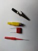
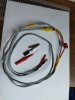
That’s my homemade “poor man’s signal tracer”.

I used unshielded speaker cable, if shielded RCA cable is the better choice or a film capacitor below 1uF, just give me hint.

Used this one as master copy, many thanks to @merlynski as well.
https://audiokarma.org/forums/index...ing-for-some-help.948992/page-3#post-14543815

I like the 4mm bananas at the end, that makes it more flexible with different probes. If necessary we can isolate the needle probe, just to leave a very small part on the tip.

Whoever wants to do the same, that are the parts I have used:
  • polypropylene film capacitor 400V 1uF (not polarized)
  • RCA Plug
  • 4 feet speaker cable
  • alligator clip
  • heat shrinkable tube
  • piercing needle probe
  • 2 x 4mm banana plugs
If that “signal tracer” looks suitable, we can start with further testing.
IMG_20211218_105606.jpg IMG_20211218_115805.jpg
 
Last edited:
That could work. Can you detect any audio signal at C27 on the RF board? That is connected to Pin 6 of the HA1137, but is easier/safer to access. The receiver will need to be tuned to a strong FM broadcast frequency. That should produce audio in that part of the circuit.
 
First the setup with the probe
  • Dipole Antenna connected
  • Function switch to FM
  • A + B Speakers deselected, listening with headset
  • RCA plug in playback Tape 1, black lead connected with bare chassis metal
  • Tape 1 monitoring selected
If I tap the chassis with the probe, a slight click can be heard, so I assume the probe is working.
Tested + side of C27, NO sound even with volume in the middle range
With probe still on C27 I tuned across the scale, nothing to hear. Same test again on pin 6 was negative.
So it means, no signal on Pin 6 :dunno:
 
In fm mode go back and measure record the DC voltages on the ha1137 again. Turn fm muting off. If there is no signal meter deflection, then kind of no need to hear recovered audio because you have insufficient IF level or indication to start with. All you should be hearing is noise at that point.
 
FM Function selected, Muting OFF (button depressed)
The voltage of HA1137 are with this setup as follows:
1 = 3,58 all vdc
2 = 3,60
3 = 3,60
4 = 0,0
5 = 0,0
6 = 0,90
7 = 3,60
8 = 3,60
9 = 4,67
10 = 4,60
11 = 13,40
12 = 4,50
13 = 7,40
14 = 0,0
15 = 0,0 jumping sometimes up to 2,7
16 = 0,0
 
Some background information. The simple RCA probe works fine.

As you can find in the other thread, I have two SX-737 sitting side by side.
https://audiokarma.org/forums/index...roblem-with-short-circuit-help-needed.978277/

This one here with the tuner issue and the second one still untouched and luckily with the working tuner.
So I tested the probe function on that second one, and I could hear an audio signal on pin 6 of HA1137.
Hope we can find the culprit and bring the bad tuner back an air.
 
Last edited:
Two SX-737 side by side?
a wild thought occurs:
tune each to a different station (or purported location by the dial markings)
touch your finger to the wire from F2 out to pin 1 of the HA1137
touch your OTHER finger to the same place in the second receiver. (10.7 MHz IF signal)

The RF skin effect should provide some signal transfer between the units.

If the duff unit's HA1137 IS working, but ISN'T getting an IF signal, (10.7 MHz IF signal)
the (intentional) leakage from the good unit may be enough to get some audio and meter deflections out of that detector chip.

That at least may help you differentiate FM problems to either a lack of IF reception or a non-working detector chip.
 
Wonder if there's enough RF leakage to get a 10.7 null if one tuner is @ 90.0mHz and the other is 10.7 higher (100.7). I've done that with Sansui and Fisher tube tuners but not Pioneer SS units.
 
@markthefixer I’m a bit scared. There is no wire coming out of F2 only a short trace to R21 and no chance to touch it from to top (part) side. I can see the leg on the foil side, but don’t feel confident touching pins in an open unit with my fingers.
Isn’t there no other way to continue?
 
Last edited:
@markthefixer I’m a bit scared. There is no wire coming out of F2 only a short trace to R21 and no chance to touch it from to top (part) side. I can see the leg on the foil side, but don’t feel confident touching pins in an open unit with my fingers.
Isn’t there no other way to continue?

F2 output connects "directly" to pin 1 of the ha1137
which is the closest pin TO F2.
330 ohm (orange orange brown gold) resistor R21 right next to the HA1137
is connected to F2 output, and F2 side goes through to the top side.

Fear? NOTHING to fear - will feel NOTHING - dry fingers and 12v dc see to that.

two points can be used:
pin 1 is a corner pin
resistor nub sticking through board

getting a few extra pins with dry fingers should be inconsequential.

upload_2021-12-19_4-17-53.png
 
Last edited:
Ok Mark, I trust you and did that test now. BUT nothing happened, not the slightest movement could be seen on one of those needles.
 
Had some time today and change the blue Sanyos like planned and the two 2SA725 Q8+Q9.
Was really necessary, they all had very high ESR between 11 ohm and up to 99 ohm (C40). Did use film for the 0.33 µF und 0.47 µF.

My hope was, this could help, but there was only one slight change. Before FM and AM was quiet, now I can hear some AM noise when I’m on AM but nothing has changed with FM.
What about the other 10 electrolytic on the board. Is it wise to change them as well?

Some small changes as well on the HA1137 voltage.
Now we have with FM Function selected, Muting OFF (button depressed)
1 = 2,74 all vdc
2 = 2,74
3 = 2,74
4 = 0,0
5 = 0,0
6 = 0,0
7 = 2,68
8 = 2,68
9 = 2,68
10 = 2,68
11 = 13,50
12 = 0,0
13 = 0,0
14 = 0,0
15 = 0,0
16 = 0,0
Any advice what to test next?
 
Last edited:
How many posts back did I mention that Ha1137 Pin 2 needs 13v? trace it back to the function switch and figure out why it is missing, bad switch, broken wires something like that.
If you do not use “am” wire it up permanently to 13v
 
@rcs16, I have seen your post and rechecked it again.

There is continuity between Pin 20 Power Supply, the Function Switch on Pin 7 – 8 - 9 and further on to Pin 3 and 4 on the tuner board. No problem found in that area.

Put a wire on pin 4 to supply permanently 13vdc, NO CHANGE. FM stays quiet.
There is 13,2v on pin 4 as well as on R22 560kOhm, after R22 voltage drop to 2,74v and direct to pin 2 (HA1137).
 
Last edited:
How strange
In “fm” mode and now with 13v on ha1137-pin2 to power up its IF section, remeasure all the pin voltages again for ha1137
 
@rcs16, I have to be clear. The 13,2v is now direct only on board pin 4 and not on ha1137-pin2.

Between Pin 4 board and pin 2-HA1137 there is still the R22 with 560kOhm. I have a voltage drop over R22 with 10,7 vdc, giving only the 2,74 vdc to pin 2 (HA1137).

I’m puzzled here if you expect 13v on ha1137-pin2. Even the OEM HA1137– Datasheet (page20) shows:
“Terminal 2 (DC Feedback to Input) V2 typ 1.9 V.”
Same information in the SM for Sx-737 (page 31) has in RED 1.9v for ha1137-pin2. Would like to understand and learn, why you are expecting 13v after the 560 kohm on that pin?

Do you still want the voltages from HA1137?
 
Last edited:
Setup: Function FM selected, Muting OFF (button depressed)
13v bridged from pin 3 to pin 4 tuner board AWE-043, the HA1137-pin voltages are.

1 = 2,73 all vdc
2 = 2,77
3 = 2,73
4 = 0,0
5 = 0,01
6 = 0,05
7 = 2,66
8 = 2,66
9 = 2,66
10 = 2,66
11 = 13,30
12 = 0,03
13 = 0,0
14 = 0,0
15 = 0,0
16 = 0,0
 
Back
Top Bottom