• The move to the new server is done. There are some software and database maintenance updates in process. This has us passing the hat around to help out. We appreciate any donations. Seriously, even a dollar helps. The payment page may be found here - https://www.audiokarma.org/support.html

SX-750 Power Switch

Register to hide this ad
Get bupkus from parts.pioneer. Service manuals for both should have the part # in them. Compare, but I'm thinking they should be same switch or similar enough to work in both. There is a thread on how to dis-assemble the switch and clean, file and re-assemble switch. SX-650 ASA-039, SX-750 ASA-038. These are combination speaker/power switches. I don't see any real difference on the physical switch configuration (speaker switch) or power configuration on the schematic.

Clean it 1st. This usually takes care of the flickering and arcing sounds (if that is the problem). The speaker selection positions are the same. http://www.audiokarma.org/forums/index.php?threads/we-can-rebuild-him-we-have-the-technology.372256/
 
Thanks! The controls like exactly the same, so I salvaged one from a 650 to use in a 750 that had a broken shaft. It's working great!
 
I had this problem with a 450. IIRC, there is a unused contact in the switch housing that can be swapped with the compromised one.
 
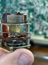
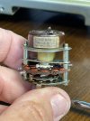
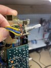
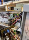
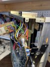
Question about SX750 Speaker Switch. My unit does not shut of when the switch is in the off position. All other positions work fine. After taking this apart, I see that the terminals on the rear of the switch have been cut. I hooked my meter up and there is continuity when I switch it on/off. Pretty sure there is supposed to be possibly a resistor attached to both terminals? I've attached some pictures. Please let me know what you see here.
 

Attachments

  • IMG_9734.jpeg
    IMG_9734.jpeg
    104.1 KB · Views: 121
  • IMG_9733.jpeg
    IMG_9733.jpeg
    96.4 KB · Views: 37
  • IMG_9732.jpeg
    IMG_9732.jpeg
    83 KB · Views: 41
  • IMG_9731.jpeg
    IMG_9731.jpeg
    101.6 KB · Views: 37
  • IMG_9730.jpeg
    IMG_9730.jpeg
    118.8 KB · Views: 34
  • IMG_9729.jpeg
    IMG_9729.jpeg
    107 KB · Views: 35
Line power should be routed through that switch. Someone has been in there modifying.

index.php


This might be informative:

 
Thanks for the great info. I think I'm getting a handle on this. I think the on/off portion of the switch (where the noble sticker is) is working. It has continuity when switched on, no continuity when switched off. Not sure why someone would've disconnected the terminals in the back. So, is C3/C4 the MOV-X/Y capacitor, .01 cap? Are both the same caps? And lastly, it looks like the thicker yellow/Orange wires are soldered to the back of the switch?
 
There is a good chance that the switch has marginal contact, and while your meter can read through it there may be resistance under the load of the receiver. That's not uncommon, and causes the lights to flicker, power supply to fall off, and the associated problems. The linked thread showed the details of opening and repairing the switch to resolve that problem, yet it seems that someone previously simply bypassed that one instead of repairing it.

As for the wires attached to the two switch lugs, the colors may or may not be consistent depending upon the sub-model of SX-750. There were "S" and "KU" and "KC" and "HG" sub-models depending upon the intended market. On the "KC-KU" models I have, the power wires are white/red on one of the units, brown/yellow on another, and the other two I have no clear view of without opening them.

In other words, follow the power cord connections and load connection to the switched receptacle and FU5, and those should be the wires. Since they are no longer on the switch, we can only guess where they might be tied.

 
If you do repair the switch (or if it works but is marginal), you should install a "Triac Modification", to take the AC load off the switch. there are many threads about this modification. It only requires an insulated tab TO-220 triac (like BTA12-600B 12 amp 600 volt insulated tab) and a 220 ohm resistor. The switch signals the triac to conduct between MT1 and MT2 when the gate is connected to MT1 through the 220 ohm resistor. This modification takes the AC load off the switch.
 
There is a good chance that the switch has marginal contact, and while your meter can read through it there may be resistance under the load of the receiver. That's not uncommon, and causes the lights to flicker, power supply to fall off, and the associated problems. The linked thread showed the details of opening and repairing the switch to resolve that problem, yet it seems that someone previously simply bypassed that one instead of repairing it.

As for the wires attached to the two switch lugs, the colors may or may not be consistent depending upon the sub-model of SX-750. There were "S" and "KU" and "KC" and "HG" sub-models depending upon the intended market. On the "KC-KU" models I have, the power wires are white/red on one of the units, brown/yellow on another, and the other two I have no clear view of without opening them.

In other words, follow the power cord connections and load connection to the switched receptacle and FU5, and those should be the wires. Since they are no longer on the switch, we can only guess where they might be tied.
got it! I will pull that thing apart again and get into the switch part to see how it looks. So is there a wafer type capacitor .01, 250v tied to both lugs?
 
If you do repair the switch (or if it works but is marginal), you should install a "Triac Modification", to take the AC load off the switch. there are many threads about this modification. It only requires an insulated tab TO-220 triac (like BTA12-600B 12 amp 600 volt insulated tab) and a 220 ohm resistor. The switch signals the triac to conduct between MT1 and MT2 when the gate is connected to MT1 through the 220 ohm resistor. This modification takes the AC load off the switch.
I do remember seeing that modification. I'll look up those threads again and probably end up doing that too. thx!
 
Back
Top Bottom