• The move to the new server is done. There are some software and database maintenance updates in process. This has us passing the hat around to help out. We appreciate any donations. Seriously, even a dollar helps. The payment page may be found here - https://www.audiokarma.org/support.html

SX-780 Issues / PA3004?

Got my parts in and installed per instructions. Below are the voltages. Still no love

IMG_9389.jpg
 
The voltages on Q25 and Q19 are good, those regulators are working.
Did you replace Q22? That is the transistor that does the feedback that controls the voltage through Q20. It and Q20 should be replaced at the same time without powering up between changing them.
Q21 is in the positive regulator and should not have negative voltages on it, misprint as 'Q21' on your drawing (as KSA992) maybe?
The base of Q22 should be -0.6vdc, the emitter sb 0vdc and the collector about -40.1vdc.
Also did you replace C310? What did you put in there, if so?
 
Last edited:
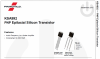
Remember lead order is reversed between the original 2SA904 and the KSA992 replacement for Q22.
2SA904crop.png
KSA992crop.png
 
Last edited:
ok,

replaced Q22 and Q20 and it works now! Whew man, what a chore learning this stuff. Glad it's fixed so I can get back to tube amp and make the rent :). I HIGHLY appreciate everyone's input and help. Diving into this from what I do now sure makes a guy feel like rookie :).
Again, thank you to those of you helped me limp along.

Mike
 
This is a Very Informative Thread on the exact issue that I am seeing on my 780 as well.

Unfortunately I have replaced Q20 and Q22 together, more than once, with brand new components and still
no love from the receiver.

Currently on Q22 I am seeing the following voltages. Emitter= .687 Collector=.687 Base=.00

As you, merlynski, obviously know this circuit both inside and out I am hoping for some help here.

Any help would be greatly appreciated...
 
I think . . . we all miss Merlynski.
@Scheid sadly you're not gonna see a reply, huge loss for us on here. Thanks to other experts who carry on for the cause of fixing these old receivers.
 
We all miss Merlynski dearly - he will not be easily replaced! I'll give helping you a shot. It seems like your Q22 base voltage isn't right - it should be -0.6V. You should definitely double check if you have Q22 and Q20 installed correctly. If those look good, I would want to look at the +-39.5V rails to make sure those are ok - there is only a voltage divider to get the -0.6V at Q22b, so it read as that - you can check it with Q22 out of the circuit to be sure!
 
Thanks for the reply. I finally got this issue fixed today. Thank God...

It turns out that this little Q22 circuit is a total mess in the Pioneer documentation as well
as on a LOT of old threads here... The schematic and the board layout diagram don't agree
on this circuit where Q22 is concerned.

Also the Silkscreen on the board itself shows the Emitter arrow pointing to the wrong side of Q22.

If someone replaced the original component (2SA904A) with the KSA992 or KSA1013, didn't know that the pinout had switched between the components, and just put it in "incorrectly" according to the E indicator arrow on the board they would be golden.

I guess in this case ignorance IS bliss after all.

If you know that the replacement component is the opposite of the original and then followed the E arrow on the silk screen when you installed it then
you would have some serious problems. Which is exactly what I was just fighting for 2 weeks.

Fortunately merlinski had straightened out this issue here in Post #55.
https://audiokarma.org/forums/index...-voltages-at-stks.944917/page-3#post-14458814

Robert Amour's Photo in Post #57 is the only picture that I would trust if you have this same issue and want to
get your negative voltages corrected.

Thanks again to merlynski, RIP, and Robert Amour for the clear and concise information clearing this up for me.

Scheid.
 
Last edited:
Back
Top Bottom