• The move to the new server is done. There are some software and database maintenance updates in process. This has us passing the hat around to help out. We appreciate any donations. Seriously, even a dollar helps. The payment page may be found here - https://www.audiokarma.org/support.html

SX-850 refurbish

madders

Active Member
Hi all,

I bought a broken Pioneer SX-850 off eBay a couple of years ago with plans to fix it up. Cosmetically it looks great, but it doesn't turn on.

I just signed up for an account here so I could download the tuning fork guides. I've also seen there's loads of information on here already where people have recapped the same or similar amps (it's a great forum!). But reading through all the old threads, I realise I'm way out of my depth - I don't even know how to use a soldering iron.

There is something burnt out on the power board, so my original plan was try to fix that - then once working, recap everything else, clean it up and do as much preventative maintenance / improvements as I can (following all the advice that's been given on here previously).

But now I'm thinking about paying someone to do the work, but I have no idea if that is feasible - especially if it's such a huge job. Does anyone have any experience with this? I'm in the UK. How do I find someone reliable who will do a good job? What is a reasonable amount to pay? (I'm guessing it's more than I can afford)

I'd really like to get it working and refurbished to a decent standard because the amp looks great and I want to use it. I have to admit I bought it based purely on looks (since I've never heard one) - but from what I've read it should sound great too.

If anyone has any advice, or can recommend someone who could do the work please let me know.

Thanks,
Michael
 
Register to hide this ad
I don't know anyone who does these repairs in your area. However, if you have never used a soldering iron then this would not be the unit to learn on. You also need to have knowledge of what the various electronic parts are and know how to use a meter. Hopefully someone else can refer you to a qualified repairman.
 
Yeah this is what I thought. My Dad used to be pretty good at this sort of stuff (he had a soldering iron and meter at least), but I think this is beyond him (and he's old now). I was planning to take the amp home over Christmas, I printed out all the schematics so I could go through them with him to try to understand what was what. But then I started looking into what I might need to buy, then came across this forum and spent a lot of timing reading other threads and realised how complicated it all is!

I'm curious if anyone knows typically how long a full refurbish of this amp would take, and how much a decent repairman would charge? If for example, it's 50 hours and I should expect to pay £20 ($30) an hour, then it's going to be too expensive!
 
I do not think I would bill 50 hours for a refrub but I think I would bill at least 25 hours@$30/hour plus parts. gee my mechanic charges $75/hr to fix my car/truck, so i guess us eTechs are lower on the pecking order.
It does depend on exactly what you are doing. That is about 3 full days on it for a complete refrub. Still $750 plus parts is probably way more than you paid for it to begin with. Big diff between getting it running again and do a complete refrub! Although a complete rebrib is the right thing to do if you want to increase reliability.
The only way economics would work, is if I work for a bag of rice, like they do in China :-)
 
This is exactly what I was thinking - I had a plumber round recently and he was charging £50 an hour!

I paid £120 for it ($180). Not exactly a bargain for something which is broken I know. But on the outside it's immaculate. At the time I figured I could fix any problems on the inside easier than any cosmetic problems on the outside!

I want to use the amp for all my music so a complete refurb is what I'm looking for really. It would bug me if I knew it wasn't in top notch condition!
 
Michael, welcome to AK!

You are at a place I was, not too long ago. My SX-850 needed work, and I contemplated having it done. Instead, I decided to tackle it myself, even though I had never soldered anything before. I bought my tools, practiced a bit, researched more, and since then have recapped two SX-850's, a PL-630 turntable and my SG-9500 equalizer. And you can do it, too, if you are reasonably mechanically inclined.

I was successful because I got some great help along the way; the AK community knows their stuff. And if you're able to put in the effort, you will get the support you need to see it through. These guys are the best.

Good luck whichever you decide!

Jeff
 
Madders - Is there such a thing as a thrift store or second-hand shop in your area? If so, it may be helpful to acquire an electronic item of a similar vintage. or at least something with through-hole mounted devices, and practice your desoldering and soldering skills on it. Once you have achieved some proficiency at removing components without damaging them and can resolder them in place without damaging the components of the circuit board, it may be time to tackle the receiver project. A 30-40W solder iron and possibly a solder sucker, solder wick braid, flux, and 60/40 solder should be a good start. There is no need to have a grounded tip solder iron for this kind of work, but there is no harm in using one either.

Regarding the burned component, can you post a photo of the damage? That might help us to identify it and speculate as to the cause(s) of the apparent failure.
 
It is probably not necessary to rebuild the entire receiver. I have a Pioneer SX-1050 that I bought new in the late 1970s. About 4 years ago one channel of the receiver stopped working. I found a local tech who works on vintage equipment. He charged me $30 to diagnose the problem and $60 more to fix it. It turned out that a couple of transistors went out (not the output transistors) which caused one channel to stop working. The receiver sounds great with powerful clean bass and great tone overall. Others have heard this receiver and also said it sounds great.

I also got a Pioneer SX-1980 about 6 months ago. The power supply had the capacitors replaced and the transistors regreased and is otherwise original. It also sounds great.

If money is limited, find someone locally who works on older equipment and have them fix the problem. The power supply board probably needs to be repaired and possibly needs to be rebuilt. Just do what you can afford to do now so you can enjoy the receiver for a while. You may be happy with how it sounds without a total rebuild. If you want to have more work done to it, save up and do it when you can afford to do it.
 
Thanks for the replies.

hertzdonut - thank you. This is what I wanted to do when I bought the amp, and encouraging to know it can be done!

jeffpaletz - I'm going to look into this, the difficulty is finding someone locally who I can trust. And you're right, I should just get it fixed first to see how it sounds before refurbishing the whole amp.

Watthour - thanks. I think this might be the answer. I could have a practice over Christmas and see how I get on before deciding what to do with the amp. Thanks for the advice on what to get.

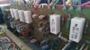
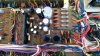
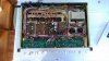
I have attached a couple of pics of the receiver. I realise now the burnt bit isn't on the power board - it's on the vertical board you can see from the top. I've also attached a couple of pics of the bottom.

IMAG1007.jpg

IMAG1009.jpg

IMAG1012.jpg
Thanks all!
 
That looks like the bias pot, a 100Ω adjustable. The concern is that it is in the circuit with the thermal compensation diode, STV4H attached to the white covered leads shown leaving the circuit board right above the damaged trimmer. Be VERY careful of those diodes since they are irreplaceable. If the leads are shorted that pot may have failed as a result. If the diode is damaged there will be extra effort to resolve the problem.

You should be able to find a suitable trimpot replacement at Farnell in the UK, among other places. Something like this should work: http://uk.farnell.com/bourns/3296w-1-101lf/trimmer-25-turn-100r/dp/9353160 . It should be able to handle the 50mA or so in that circuit.
 
Awesome! Thanks for the information (even though I didn't understand it all). Not sure if I'm going to attempt to fix this myself yet - need to do a lot more reading and practacing first if I do.

I just have one dumb question. If I replace the part will it not just burn out again?Should I be trying to figure out what caused it to burn out?
 
On an amp, there is always more unseen damage.
Very fixable with little expense, mostly labor time.
 
Well I decided to have a go fixing this over Christmas, but I've got a bit stuck now, hopefully someone can confirm I'm heading in the right direction. Here's what I've done so far:

1. Replaced the VR4 pot. But made a bit of mess desoldering (I did practice on an old TV first).
2. Resistor R38 and R40 started smoking. I'd made a DBT and it did go dim (with 100W bulb). I checked where I'd soldered the VR4 pot and it wasn't making a good contact - I had to scratch a bit of the track off and put a blob of solder there. Also the pot was getting very hot.
3. I checked the output transistors and found Q14 and Q16 were shorted.
4. I replaced resistors (R38 and R40) and transistors (Q14 and Q16).
5. Now the DBT goes much dimmer (looks like it was off), nothing is smoking but the relay isn't clicking.
6. I followed the steps to adjust the bias and offset. The voltage at pin 25 is 18V, adjusting VR4 changes it slightly, but it's impossible to get down to 0. The voltage across 27 and 28 is 5mV and adjusting VR2 made no difference. All the voltages on the other half of the board are correct.
7. I replaced Q2 and Q4 based on advice in other threads saying these can cause problems, but it made no difference.
8. Then I carefully tested the voltage on Q6 and Q8, and the voltage on the collector is about 38V on both (should be 1.2V according to the manual). So now I've ordered replacements for these. Not sure if this is going to fix the problem though.
 
madders.....stick with it. I,m somewhat slightly ahead of you in using a soldering gun and such,but not by much! I bought an SX 850 also that has the familiar "no relay click" issue that many have run into. I,m learning alot from the people on here. With a little practice and a little reading it can be a very rewarding fix! Good luck.
 
I may be following along shortly. I just got some newly-pressed vinyl and about 2 minutes into Track One the phono preamp went noisy on me. I'm guessing it's the 725s so it will be coming out of the rack for rework (finally). If you need any comparative voltage measurements, I'll have one open on the bench. I hope I have most of the caps I need.

I've switched over to the table connected to my 950 for entertainment while I work.
 
Sorry Madders, you went about this the wrong way.
Many here believe, just rebuilt it and the problems will be fixed = a crap shoot. Looks like your luck in craps is not very good. You may have better luck at darts.
Many give this blinded advise to do a mass change out of parts or even specific parts as in this case because they themselves struggle to understand electronics and troubleshoot the circuits correctly and sufficiently before ever powering up the unit or turning on a soldering iron. So you are back to square one again and dug a hole in the process. This time, do some ohmmeter measurements comparing the channels to isolate problems.
3. I checked the output transistors and found Q14 and Q16 were shorted.
This should have been step one. ? is were they fried before or after your handiwork. Many times the o/p bjts are the cause of the fault, so a quick ohmmeter test, removal/replacement of them, solves the problem.
1. Replaced the VR4 pot. But made a bit of mess desoldering (I did practice on an old TV first).
Should have done an ohmmeter test on this part and every other part in the circuit beforehand, to assess its condition and after you changed it. people recommend to change the part, I do agree, but at the right time, as it does oxidize and lose contact and results in what you experienced with it being open circuit. But then again the assumption was that this part was the problem to begin with and I am not so sure about that.
First rule of holes is quit digging. Sorry I could type a book on how to troubleshoot your circuits, done it before and people just went ahead and ignored my advise and just kept digging.
good luck, maybe the new year will bring more luck to your electronics.
 
Last edited:
You're right, I don't fully understand what I'm doing and my handywork probably has caused more problems! I'm learning quite a lot though. I changed VR4 because it was burnt - it was melting. And the cause appeared to be the output transistors. Now I've changed them, it's no longer getting hot.

I've now changed both Q6 and Q8 and the voltage on the collector of both is still wrong, it's around -48V. I thought the incorrect voltage was caused by the transistor, but could it be something else in the circuit?
 
Well I read up a bit more on transistors, came to the conclusion there must be something wrong with one of them, I rechecked and found I had put Q8 in the wrong way round - I thought I had been really careful to make sure it was correct, but obviously not! I put it in the correct way and now it's working! Woohoo! Only tested with headphones so far but sounds pretty good.
 
It might be worthwhile to check Q10/12, D8/10, and D4. Verify that C16 and C18 are not shorted.

I presume the unit is operating at 230V, so the DBT could use a 50/60W lamp instead of the 100W which might not limit current quite enough.
 
Hi Watthour, I guess you wrote that before I said it was fixed. Thank you for all your help, I don't think I would have bothered trying if you hadn't recommended the replacement trimmer in the first place.

It is 230V, but I thought with a DBT, higher watt was better? I wanted to get a 150W bulb, but very hard to find these days!

Not sure what to do next. Since I've had the power amp board flipped over so many times, I thought I might at least replace any other recommended components on that board before putting it back. Then I'll clean it up, but it back and hopefully never need to flip it over again.

So far I've changed VR4, Q2, Q4, Q6 and Q8. I also have 10k trimmer VR2, but haven't changed it yet. I ordered two of everything, so I could change the corresponding components on the right side of the board VR1, VR3, Q1, Q3, Q5, Q7. Should I also do the capacitors? I know there are plenty of lists on here with replacement capacitors for this board. Is it worth doing the remaining transistors too?
 
Back
Top Bottom