• The move to the new server is done. There are some software and database maintenance updates in process. This has us passing the hat around to help out. We appreciate any donations. Seriously, even a dollar helps. The payment page may be found here - https://www.audiokarma.org/support.html

SX-850 refurbish

I don't know what happened, but the voltages look good now. Maybe my old DMM was faulty.
Well that is good, it fixed itself :-)
Should I expect some noise?
yes, more than the other inputs,aux, as it has more gain, around 35dB@1KHz, so it amplifies the noise a lot more. RIAA equalization helps a bit.
Put an LP on and set the vol to the same setting, as when you did your noise test, see if you hear the noise now :). LP surface noise will prevail if you can stand that volume.
Enjoy it, i think you are near done.
 
It may be helpful to connect a 1K resistor at the phono input jacks to see if the noise floor is reduced. The routing of the shielded coaxial cables from the input jacks to the phono board under the chassis can pick up noise. The resistance can bleed some of that off to help identify the source.
 
Well that is good, it fixed itself :)

yes, more than the other inputs,aux, as it has more gain, around 35dB@1KHz, so it amplifies the noise a lot more. RIAA equalization helps a bit.
Put an LP on and set the vol to the same setting, as when you did your noise test, see if you hear the noise now :). LP surface noise will prevail if you can stand that volume.
Enjoy it, i think you are near done.

Thanks - I am enjoying it :)
I don't have a turntable yet, so I can't put a record on! I'm looking out for something like a Pioneer PL-570. But I get the idea, even with the volume turned just a quarter of the way round, it's very loud. It's crazy how loud it gets.

It may be helpful to connect a 1K resistor at the phono input jacks to see if the noise floor is reduced. The routing of the shielded coaxial cables from the input jacks to the phono board under the chassis can pick up noise. The resistance can bleed some of that off to help identify the source.

I can give this a go. It would be good to know for sure if the noise is to be expected or not (even if I am never going to have the volume that loud). What watt resistor should I use? And exactly where / how would I connect it? Thanks!
 
I just tried this. I think I got it right because it has made a difference. I did two and put them in the Phono 1 inputs. I've attached a photo.

I'd say the noise level is at least halved. Switching to Phono 2 is much louder. It's still not as quiet as the Aux input though (but almost).

So does this mean there is a problem?

IMAG1084.jpg
 
So does this mean there is a problem?
I still do not think that you have a problem.
When you switch to phono 2 the 1K input terminators should also be placed at its input for that test.
The phono stage will never be as quiet as the AUX input.
 
This can indicate that there is EMI bleeding into the highly sensitive Phono inputs and is being amplified. The routing of the signal cables from the rear panel to the phono amp board are supposed to be somewhat shielded. Radiated signal and noise from within the unit could be reaching the inputs due to cable routing, marginal grounds, and poor cable and component shielding can affect this.
 
I've noticed that the sound from one input can be heard on the other inputs when the volume is turned right up. For example, I had my phone connected to the Tape 1 inputs, and I left it playing when I flipped the tape 1 off and switched to Aux. When I turned the volume up I hear the music. I had the volume turned very high, but the music was very noticeable. So I started playing around, and I found FM could be heard when the Tape inputs were flipped. Although Tape 1 was louder than Tape 2.

Is some level of leakage between the inputs to be expected?

I'm guessing this is all related to the phono noise problem, and either it's to be expected, or I've messed something up - maybe with the cables, but I thought I put everything back as it was.

I'm going to leave it for a couple of days I think - it's nice just being able to listen to it. But when I get some time I'll have a play with the cables and see if moving them around makes any difference.
 
Some signal bleed at high volume levels is not uncommon on these units. The SX-1250 has metal shields covering several of the sub-assemblies to help prevent crosstalk and EMI. Grounding of each circuit is important as well.
 
I had a dig around today to see if I could figure out if the signal bleed was a problem or not.

I unclipped all the cables and separated them out as best I could, and moved them away from the boards, but it made no difference. So I think I can rule out any issues with the cables.

I've also cleaned all of the switches again, but it's made no difference.

I've tested the different inputs. The worst signal bleed is from Aux to either of the Phono selectors. At half volume it's very clear and easy to hear what's playing on the Aux input. It's slightly louder on Phono 2 than Phono 1. After a while I realised it's only one channel that I hear the music on, the other is just hiss. I cleaned the Aux and Phono selector switches again, but it made no difference. I've tried to follow the schematic to figure out what the cause could be, but I'm stuck. The fact it's only one channel I can hear implies there is definitely a problem, and it's the same problem on both Phono 1 and Phono 2.

I know it's not really a big deal, but it's annoying that something is wrong.
 
If you study the schematic it is apparent that the NC contacts of S15 are intended to ground out any AUX input signal when it is not selected. This is to eliminate any of that crosstalk. Similarly, the PHONO selector switches S13 and S14 ground their respective input signals when they are not selected. The fact that the noise is more apparent in one channel would lead me to believe that one of these switch contacts is not performing as it should.

There is a 100Ω resistor at each of these inputs to prevent dead-shorting the inputs to ground when the functions are not selected, and it MAY be possible that these resistors themselves or their foil traces are broadcasting to the other inputs' resistors or traces.

If those switches are resistive or their ground continuity is not reliable some of that signal might bleed to other inputs. Grounding between Pins 26/27/28 and Pins 14/16 needs to be absolute. It wouldn't hurt to clip a test lead between these grounds to see if it improves the situation, since these are not interconnected on the board itself.
 
Hi Watthour,

I already saw the switches on the schematic, and that S15 connects to ground. But if the input signal on aux is grounded, could it not be picked up somewhere else that is also connected to ground?

I thought the same about the switches being the cause as it's affecting one channel more than the other, but I've cleaned them many times and it's making no difference at all.

I looked at the foil traces - I even reflowed a couple that looked a bit close. And I've tried the test clip between the ground pins. Not sure if I was supposed to test the voltage there? It was 0V anyway.

When I flip the tape monitors with a source playing on Aux, it's also audible when the volume is turned right up (from reading other threads, I believe this is to be expected on the tape loops). But it is exactly the same volume in both channels (and quieter than the leakage to the phono inputs). So I'm thinking it's not the Aux switch causing the problem because the difference in channels is not present with the tape inputs selected. Similarly, since the behaviour is the same on both Phono 1 and Phono 2, I don't imagine it's either of those switches. It makes sense that it's something on the function switch board causing the problem - like the Aux signal at pin 17 leaking to pin 19. But I've cleaned the board, inspected it lots of times, poked and prodded it but I'm having no luck.

I took another look at the input jacks at the back. There are tiny capacitors at each input, connected from the ground of the input to the back of one of the screws securing each input. It doesn't look original, since they are soldered (and the other wire wraps aren't soldered). But I just noticed them on the schematic (C5, C6, C7). Then I noticed the one on the Aux is missing. I've attached a couple of pictures. Could this be the problem?

IMAG1153.jpg IMAG1155.jpg
 
I believe those caps may be on an equalizer amp board for those functions, but am not positive. I have no way to check for a few days since I am doing service in Texas this week. You might be able to discover that faster than I can.
 
It is a problem to eliminate all the crosstalk in an amp or receiver. In receivers, that is why they cut the power to the tuner when it is not selected. When using other line level sources you might experience crosstalk. When using an amp with an outboard tuner you might get crosstalk.

Some older preamps shorted the inputs that were not selected to get rid of this, but that is no longer practical because it may overload the line output buffers of certain things like tuners, tape decks, CD players.

It is probably best to just turn off the sources you're not listening to at the time.
 
Yes I've come to the conclusion it's just how it is.

I've spent a couple of days with the receiver in pieces trying to see if I could get rid of all the crosstalk and noise. No luck, but I made some interesting discoveries:

I found that when using the continuity test on my new DMM, if there is an audio signal, I can hear it playing through the DMM.

I wanted to be sure it wasn't the switches causing the problem, so I took apart the most likely culprit (the aux selector switch). I was pleasantly surprised to see it was very clean and shiny inside. So at least I can be fairly confident all the switches are clean. It was quite easy to get inside - I had de-soldered the pins at the bottom, but then realised I didn't need to. I've added a couple of pictures below if anyone is wondering what the inside looks like.
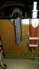
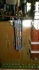
IMAG1156.jpg IMAG1157.jpg

I disconnected some of the different stages to see if I could isolate the problems. It's actually not that difficult to unwrap the wires around the pins, and put them back after. Regarding the noisy phono inputs, I found that if I disconnected the inputs completely at pins 3 and 5 on the equaliser board, it was still just as noisy, so I guess it is just the level of amplification done by the equaliser board (and not something picked up by the input jacks or wires to the board).

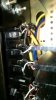
I managed to eliminate the aux left channel leaking to the phono inputs by disconnecting the aux input wire at pin 17 and connecting it directly to the appropriate aux switch pin (I also took the 100k resistor off the board and put it between the wire and the pin). I've included a picture below. Like this, even at full volume I couldn't hear anything on either phono input (and it did play fine when I selected aux).
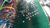
IMAG1160.jpg

I've cleaned the board - especially round that track and all round the pins, but I can't see anything suspicious. I'm just assuming it's because the pins are so close together? And it is specifically the left channel from the aux source playing through the right speaker on the phono input, and it's about twice as loud on phono 2 than phono 1.

I put it back how it was, I'm not ever going to have aux playing at the same time as phono so it doesn't really matter anyway. And I think it'll be better to use the tape input rather than aux, since that skips the switch assembly board all together.

 
I think I may have mentioned the "broadcasting" concept in an earlier thread. You may have just discovered that.
 
It appears that the designations may have been mixed up there. On my copies of the schematics the readings are shown as:

Q5 C, 1.55V
Q5 B, -18.4V
Q6, C, 1.55V
Q6, B, -18.4V

View attachment 681877

Old post, but thanks Watthour for putting this out there. I was scratching my head trying to figure out why my readings on the collectors of Q5 and Q6 weren't jibing with the schematic I'm using.
 
Back
Top Bottom