

You are using an out of date browser. It may not display this or other websites correctly.
You should upgrade or use an alternative browser.
You should upgrade or use an alternative browser.

Q10 is the device in question on either the 850 or 950. The suspicion is that the higher frequency devices may approach oscillation and elevate the E-C conductance without adequate load. Adding parasitic load to rectify the problem may be a band-aid, but using a slower device (like the original 4MHz) seems to solve it nicely.
I was looking at the specs for the original 2SC869 from this site: http://www.datasheetarchive.com/dlmain/Datasheets-X2/DSA1206000-37.pdf it shows 4-6 MHz for that family of Mitsubishi devices.
This probably explains it more thoughly/effectively: http://audiokarma.org/forums/index....-i-select-speakers.698487/reply"e=9360530
The 2N5551 is shown at 300MHZ on some sites and 100 MHz from OnSemi under load conditions.
Then again, if you want to be careless and fat-finger it like I did (and to confuse matters more) you can plug in "2SC5551" which is shown at 3.5 GHz from Sanyo. That'll get your attention!
Datasheets all over the interwebs show various values for any given component. It always seems safest to find those closest to the OEM for reliable data.
This probably explains it more thoughly/effectively: http://audiokarma.org/forums/index....-i-select-speakers.698487/reply"e=9360530
The 2N5551 is shown at 300MHZ on some sites and 100 MHz from OnSemi under load conditions.
Then again, if you want to be careless and fat-finger it like I did (and to confuse matters more) you can plug in "2SC5551" which is shown at 3.5 GHz from Sanyo. That'll get your attention!
Datasheets all over the interwebs show various values for any given component. It always seems safest to find those closest to the OEM for reliable data.
I'm having some problems with the equalizer board (I fixed the KSA992 that was in the wrong way). Some of the voltages are way off. It's Q5 and Q6 (the KSC1845s) that are the worst:
Q5 C -18.6 (15.5v)
Q5 B 1.5 (-15.36v)
Q6 C 23 (15.5v)
Q6 B 17.1 (-15.36v)
And the resistor R18 is way over too:
R18 27.1 (0.55v)
I've doubled checked all the components I've changed and they all look good and are in the right way. It's also really noisy on both phono inputs (sounds like wind coming out of the speakers) and I've deoxited the switches twice.
Q5 C -18.6 (15.5v)
Q5 B 1.5 (-15.36v)
Q6 C 23 (15.5v)
Q6 B 17.1 (-15.36v)
And the resistor R18 is way over too:
R18 27.1 (0.55v)
I've doubled checked all the components I've changed and they all look good and are in the right way. It's also really noisy on both phono inputs (sounds like wind coming out of the speakers) and I've deoxited the switches twice.
Yes I've been using the DBT the whole time until today (so when I switched the KSA992 round the other day I was using DBT). I've pretty much finished changing everything, and bulb was dim, so I went to house power, set the dc offset and idle bias, all seemed well. I decided as a final check to go through every board and checked each voltage marked on the circuit diagram (which has taken me ages!), thats when I noticed these, so these readings are on house power.
 I already checked a couple of times nothing was in the wrong place. You can just about see on the photo the transistor names for the three on the left. The inner one is definitely 992, and on the right hand side it was the 992 that was in the wrong way round.
I'm having some problems with the equalizer board (I fixed the KSA992 that was in the wrong way). Some of the voltages are way off. It's Q5 and Q6 (the KSC1845s) that are the worst:
Q5 C -18.6 (15.5v)
Q5 B 1.5 (-15.36v)
Q6 C 23 (15.5v)
Q6 B 17.1 (-15.36v)
And the resistor R18 is way over too:
R18 27.1 (0.55v)
It appears that the designations may have been mixed up there. On my copies of the schematics the readings are shown as:
Q5 C, 1.55V
Q5 B, -18.4V
Q6, C, 1.55V
Q6, B, -18.4V
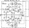
Thanks Watthour - this helps a bit, but there are still some major differences (and the noise).
I noticed that on the large schematic I have, the voltages are the same as the image in your post (the version I have is in colour, the voltages are in red and very easy to see).
However, the voltages on the page with the picture of the board are different, and they were the ones I was using.
In addition I think I must have got my Q5 collector and base the wrong way round. So including the Q3 and Q4 readings, and using the voltages from the big schematic (or your attachment), I've just taken the readings again.
The right side of the board looks good:
Q3 - Emitter: -18.6 (-18.3)
Q5 - Collector: 1.57 (1.55)
Q5 - Base: -18.4 (-18.4)
However, the left side is way off - I'm getting positive voltages where they should be negative:
Q4 - Emitter: 17 (-18.3)
Q6 - Collector: 23 (1.55)
Q6 - Base: 18.1 (-18.4)
So something is not right on the left side of the board, but I don't know what. Are there any likely candidates?
Thanks!
I noticed that on the large schematic I have, the voltages are the same as the image in your post (the version I have is in colour, the voltages are in red and very easy to see).
However, the voltages on the page with the picture of the board are different, and they were the ones I was using.
In addition I think I must have got my Q5 collector and base the wrong way round. So including the Q3 and Q4 readings, and using the voltages from the big schematic (or your attachment), I've just taken the readings again.
The right side of the board looks good:
Q3 - Emitter: -18.6 (-18.3)
Q5 - Collector: 1.57 (1.55)
Q5 - Base: -18.4 (-18.4)
However, the left side is way off - I'm getting positive voltages where they should be negative:
Q4 - Emitter: 17 (-18.3)
Q6 - Collector: 23 (1.55)
Q6 - Base: 18.1 (-18.4)
So something is not right on the left side of the board, but I don't know what. Are there any likely candidates?
Thanks!
Is C18 in good condition? In the photo it appears to be oriented correctly.
Is Q6 damaged? It may have to be removed for testing.
It might also be helpful to check C12, R18, and look for solder bridges or other connection issues around that area, although it seems that you have already done so to some extent.
Is Q6 damaged? It may have to be removed for testing.
It might also be helpful to check C12, R18, and look for solder bridges or other connection issues around that area, although it seems that you have already done so to some extent.


It was Q6! Thanks for the pointers Watthour. When I tested it there was no conduction from the emitter to the base. Perhaps it was damaged when I had Q2 in the wrong way round. Luckily I had a spare KSC1845 so I could change it straight away. Now the voltages are all spot on!
I've found one other problems with my voltages, this time on the flat amp board. On Q1 an Q2 the base voltage is below the emitter voltage - although everything is within a few percent of the schematic voltages:
Q1 - E: 28.1 (28.5)
Q1 - C: 45.7 (47.5)
Q1 - B: 26.8 (29.1)
Q2 - E: 28.3 (28.5)
Q2 - C: 45.8 (47.5)
Q2 - B: 27.0 (29.1)
rcs16 said previously this means the junction is in reverse bias. Does this mean these transistors are faulty? I think these two transistors and Q3 and Q4 on the same board are the only transistors I haven't replaced in the entire receiver (excluding the tuner board). I don't think I've seen any threads that recommend these need changing.
I've found one other problems with my voltages, this time on the flat amp board. On Q1 an Q2 the base voltage is below the emitter voltage - although everything is within a few percent of the schematic voltages:
Q1 - E: 28.1 (28.5)
Q1 - C: 45.7 (47.5)
Q1 - B: 26.8 (29.1)
Q2 - E: 28.3 (28.5)
Q2 - C: 45.8 (47.5)
Q2 - B: 27.0 (29.1)
rcs16 said previously this means the junction is in reverse bias. Does this mean these transistors are faulty? I think these two transistors and Q3 and Q4 on the same board are the only transistors I haven't replaced in the entire receiver (excluding the tuner board). I don't think I've seen any threads that recommend these need changing.

tsd71
RIP Tom Petty
i did say earlier in the thread that you had Q2 backwards (I said Q1 but I was backwards, too many beers maybe), this could have possibly taken out Q6 if you were on house power. When I restore an 850 or 950 I replace all the transistors on the equalizer, simple 4 KSC1845's and 2 KSA992's.
I'm glad you figured it out NICE JOB!
I'm glad you figured it out NICE JOB!
I've found one other problems with my voltages, this time on the flat amp board. On Q1 an Q2 the base voltage is below the emitter voltage - although everything is within a few percent of the schematic voltages:
Q1 - E: 28.1 (28.5)
Q1 - C: 45.7 (47.5)
Q1 - B: 26.8 (29.1)
Q2 - E: 28.3 (28.5)
Q2 - C: 45.8 (47.5)
Q2 - B: 27.0 (29.1)
rcs16 said previously this means the junction is in reverse bias. Does this mean these transistors are faulty? I think these two transistors and Q3 and Q4 on the same board are the only transistors I haven't replaced in the entire receiver (excluding the tuner board). I don't think I've seen any threads that recommend these need changing.
Q1/2 collector voltages being low may be affecting the base voltages. Since the base voltage is derived from a voltage divider (R43/R11) which is sourced from the same supply as the collector, the result may be a lower voltage, however it should be more relative to the collector voltage. Part of that voltage divider is also the internal (junction) resistance of the transistor, so that may be a problem if the transistors are damaged.
Regarding Q3/4, those are FETs, and finding currently available replacements with suitable characteristics can be a challenge. If you determine they are bad they might be replaced with BF256Bs but they are only rated for 30V - Much closer to the circuit design voltage than the original 50V devices. It may not be a good idea to replace those two as a preemptive measure if they are presently working.
i did say earlier in the thread that you had Q2 backwards (I said Q1 but I was backwards, too many beers maybe), this could have possibly taken out Q6 if you were on house power. When I restore an 850 or 950 I replace all the transistors on the equalizer, simple 4 KSC1845's and 2 KSA992's.
I'm glad you figured it out NICE JOB!
Thanks tsd71! I had replaced all 6 transistors to start with, so the Q6 that got damaged was a new KSC1845. Luckily when I had ordered them, the minimum quantity I could order was 5, so I had a spare one.
Q1/2 collector voltages being low may be affecting the base voltages. Since the base voltage is derived from a voltage divider (R43/R11) which is sourced from the same supply as the collector, the result may be a lower voltage, however it should be more relative to the collector voltage. Part of that voltage divider is also the internal (junction) resistance of the transistor, so that may be a problem if the transistors are damaged.
Regarding Q3/4, those are FETs, and finding currently available replacements with suitable characteristics can be a challenge. If you determine they are bad they might be replaced with BF256Bs but they are only rated for 30V - Much closer to the circuit design voltage than the original 50V devices. It may not be a good idea to replace those two as a preemptive measure if they are presently working.
Thanks Watthour. So I'm going take out Q1 and Q2 to test them. Since they both have exactly the same problem, I thought it was less likely there was something wrong with the transistors themselves, but I will test them and the resistors you mention. Regarding Q3 and Q4, I had noticed they looked different in the schematic, with S and D labels. Fortunately the voltage on these look good, so I don't think I have worry about replacing them.
Q3 - Source: 17.4 (17.2)
Q3 - Drain: 22.4 (22.3)
Q4 - Source: 17.1 (17.2)
Q4 - Drain: 22.7 (22.3)
The FETs voltages look reasonable. As for their performance, you can determine that once the unit is assembled and playing through speakers. I doubt that they will be a problem, but I could just as easily be wrong.
The Q1/Q2 condition needs to be assessed and the lead orientation verified. If everything is reasonable with those, the resistor values surrounding those trannies need to be verified. You seem to be on the short end of the project now, and this should go rather quickly. In other words, you're quickly running out of problems and should be able to transition to "enjoyment" mode soon.
The Q1/Q2 condition needs to be assessed and the lead orientation verified. If everything is reasonable with those, the resistor values surrounding those trannies need to be verified. You seem to be on the short end of the project now, and this should go rather quickly. In other words, you're quickly running out of problems and should be able to transition to "enjoyment" mode soon.
Yes - hopefully not too much more to do!
Everything appears to check out ok around Q1/Q2, so not sure what to do now. Q1 and Q2 are the original C1885s so I'd hope they are in the right way. I've put all the readings below in case I missed something.
Q1:
B-E: 711
B-C: 693
E-B: 1
E-C: 1
C-E: 1
C-B: 1
Q2:
B-E: 719
B-C: 703
E-B: 1
E-C: 1
C-E: 1
C-B: 1
R11: 215K (220)
R43: 118K (120)
R12: 220K (220)
R44: 119K (120)
R13: 12K (12)
R14: 12K (12)
Everything appears to check out ok around Q1/Q2, so not sure what to do now. Q1 and Q2 are the original C1885s so I'd hope they are in the right way. I've put all the readings below in case I missed something.
Q1:
B-E: 711
B-C: 693
E-B: 1
E-C: 1
C-E: 1
C-B: 1
Q2:
B-E: 719
B-C: 703
E-B: 1
E-C: 1
C-E: 1
C-B: 1
R11: 215K (220)
R43: 118K (120)
R12: 220K (220)
R44: 119K (120)
R13: 12K (12)
R14: 12K (12)