• The move to the new server is done. There are some software and database maintenance updates in process. This has us passing the hat around to help out. We appreciate any donations. Seriously, even a dollar helps. The payment page may be found here - https://www.audiokarma.org/support.html

SX-850 refurbish


I saw something like these when I was looking in Maplins the other day. How do they work? Do they connect to the existing wires on my DMM?

For a silicon junction, usually 0.6-0.7V, so for an npn to turn on, the base must be 0.6-0.7V above emitter
Q9
E - 5.9v (5.4)
C - 21.5v (16.5)
B - 6.2v (6) base is only 0.3V above emitter, this is a problem. Note, should be loaded with at least one lamp beaning turned on, so that some current is passing through Q9 C-E to the load.

Q10
E - 6.3v (5.4)
C - 21.5v (16.5)
B - 5.2v (6.1) the base voltage is below the emitter voltage, this is wrong, the b-e junction is in reverse bias = no conduction from collector to emitter.

Thanks for the information. To be honest, the readings were quite erractic, but the collector was consistently well over 21v.

It turned out all the problems were caused by the power amp board. When I was testing some of the pins, the voltages were as high as 70v (the ones that should have been 51.5v). I had a good look at the board and found that the white wire that connected pin 15 to 30 had broken. But I think it had been intermittently touching the pin. So one side of the board wasn't getting the negative voltage from the filter capacitors. Also when I looked at the heatsink I noticed a pin from one of the output transistors sticking out. It must have bent when I pushed it in. So I guess that didn't help things. After fixing this and another thorough check of everything, it's all good. The voltages are all correct on the power supply and power amp board. And I can set the dc offset and idle bias easily.

I listened to it for a while and it sounds okay. I don't really know what I'm listening for but I'd say the bass is a bit muffled at times, and the treble can be a bit scratchy (can't think of a better way to describe it). So hopefully recapping the tone and flat amp boards will improve it. I also still need to do the equaliser board as Watthour recommended. I've already deoxited all the pots and switches, I might do them again though.
 
Equalizer is easy to work on 6 transistors, 4 KSC1845's and 2 KSA992's.

Those mini grabbers work in a Fluke like multi meter, for the price they are very good, I use them all the time.

Good find on the broken wires, I always check for wiring issues before powering up.
 
Equalizer is easy to work on 6 transistors, 4 KSC1845's and 2 KSA992's.

Those mini grabbers work in a Fluke like multi meter, for the price they are very good, I use them all the time.

Good find on the broken wires, I always check for wiring issues before powering up.
I agree, the grabbers are by far the best.
Bob
 
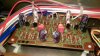
Looks like you have Q1 orientated the wrong way, maybe it's the picture.All three transistors should be facing the same way if you used KSA992's and KSC1845's. Q1 Q3 & Q5
 
Last edited:
Ah you're right, I'm glad I posted the picture. Thanks for spotting it! I did a quick test earlier and it was very noisy on the phono inputs. Hopefully this is the cause. It's not the first time I've put one in the wrong way, even though I'm extra careful to check which pin is which and match it to the board.
 
Does anyone know where I can download a full copy of the service manual? I tried lots of sites (including here), but they pretty much all have the same version with pages missing. For example there is no diagram or parts list for this board (equalizer) or tone amp or protection circuit board.
 
Thanks again hertzdonut!

What do you guys use to connect the new big filter caps? The new ones I bought have screw terminals. I've looked through as many threads as I can find on here. Seems the advice is to remove the existing wire wraps and add ring terminals to the wires. When I searched for ring terminals, I found the crimp ones. Then after more searching I found some ground terminal ones, which I think can be soldered on to the end of the wires:

http://uk.farnell.com/duratool/d01501/ground-terminal-brass-np-l-15mm/dp/1733433

Do these looks right? I don't really want to buy a pack of 100 though! Are there any good single alternatives?

Also what do I do with the resistor across the terminals? Can I reuse the one that's there? And how do I reattach it - should I add ring terminals to the resistor too?

Thanks!
 
Ring terminals are the way to go, you might have to drill them open a little to fit the screw in.IMG_0485.JPG
 
I spent ages checking through the datasheets, so the ones in the link should fit okay I think. The screws are 8mm and the holes in the ground terminals are 8.3mm.

From the pic, it looks like you have put two wires onto the same ring terminal, rather than a separate ring on each wire. Is that the recommended way?
 
It is fine, everything gets crimped and soldered together, as long as the ends are wide enough to accept two wires it good as gold.
 
Don't I have to choose crimp or solder? Is it possible to do both?

Also, how have you attached the resistors in that pic?
 
You can crimp and solder I do both for extra bond, the resistor is wrapped around the screw and tightened down.
 
I just discovered the issue I had earlier with Q9 and Q10 on the power supply board is not fixed. It turns out the voltage on the collector changes depending on whether any speaker outputs are selected. When I checked the voltages initially I didn't have any speakers selected, and they were high. I must have had one of the speaker buttons selected when I rechecked them (after fixing the broken wire). I've rechecked them all again:

Speakers A Selected / No Speakers Selected / Schematic
Q9:
E - 5.25 / 6.67 / 5.4
C - 18.65 / 21.4 / 16.5
B - 5.76 / 6.81 / 6

Q10:
E - 5.77 / 6.84 / 5.4
C - 18.65 / 21.4 / 16.5
B - 6.25 / 5.54 / 6.1

It's actually the same problem as described in this thread:
http://audiokarma.org/forums/index....-950-lamps-dim-when-i-select-speakers.698487/

I am also seeing that function selected light goes a lot brighter with no speakers selected.
 
I guess try and follow his instructions by replacing Q7 with a 2N5551, not sure why, Mark's list has worked for many an AK'er including me.

Sean
 
Back
Top Bottom