• The move to the new server is done. There are some software and database maintenance updates in process. This has us passing the hat around to help out. We appreciate any donations. Seriously, even a dollar helps. The payment page may be found here - https://www.audiokarma.org/support.html

SX-850 refurbish

I have an 850 that I originally bought for parts (thrown off a truck). After reading the many posts about finding and fixing the problems, I had a working receiver. My advice is to read, read, read. I sat for hours reading posts and looking at the schematics to see what was being said. Slow and sure, step by step works. My 850 is tucked away waiting for a deeper refurbishment. Fix the faults first and enjoy the music. The second one is so much easier.
 
With the higher voltage the current demand is lower to accomplish the same power (watts). There is no need to increase the wattage to accommodate the higher voltage, and 50/60 watts should be plenty for the first test on the DBT with an SX-850. Once you've proven there is no magic smoke on a 50-60W lamp you can increase the wattage to bring up the line voltage if necessary to get the circuit voltages close to the correct levels. Since you've already tested on a 100W and resolved the heating problems, the point is somewhat moot, but for future projects starting at a lower wattage and incrementing upward is generally safer.

Since the board is already "set free" from its mountings, changing the electrolytics is probably a good idea. The SX-850 used mostly ceramic and Mylar caps on the power amp, so changing them might not provide any benefit.

However, once the power amp board is completed you might want to flip the unit over and address a couple potential issues on the underside. The phono equalizer amp has a handful of suspicious transistors to be replaced, and the power supply board should get a good inspection. The equalizer amp has two 2SX725s and four 2SC1313s which should be replaced out of habit. The 2SA725s can be replaced with Fairchild KSA992Fs and the 2SC1313s can be replaced with Fairchild KSC1845Fs. Each of those is about three shillings. The board also has electrolytics in the signal path at C1/2 and C11/12 which could be replaced. Those are 1µF and 3.3µF caps, respectively.

The power supply should at the very least have the regulator transistors loosened and get a fresh thin coating of silicon thermal compound between their tabs and heat sink mountings. The electrolytic caps on that board may show signs of heating and should be checked closely, with any suspicious parts getting replacement. The diodes may also show heating and should be checked and replaced as necessary. If the four diodes are replaced it may be advantageous to form the leads of the replacements to allow the diodes to stand off the circuit board a few mm so that cooling air can circulate around them more easily. Any browned resistors, including those in the fire sleeves, should be checked and replaced as indicated.

 
Thanks ADKbob, I have done a lot of reading so far!

Thanks for all the info Watthour. I'm going to order the parts for the power supply and equalizer boards today. I already got thermal paste for the output transistors on the power amp board so I'll use it for the transistors on the power board.

When I'm testing the voltages should they exactly match the schematics? I've noticed some are a couple of volts off.
 
With the higher voltage the current demand is lower to accomplish the same power (watts). There is no need to increase the wattage to accommodate the higher voltage, and 50/60 watts should be plenty for the first test on the DBT with an SX-850. Once you've proven there is no magic smoke on a 50-60W lamp you can increase the wattage to bring up the line voltage if necessary to get the circuit voltages close to the correct levels. Since you've already tested on a 100W and resolved the heating problems, the point is somewhat moot, but for future projects starting at a lower wattage and incrementing upward is generally safer.

Since the board is already "set free" from its mountings, changing the electrolytics is probably a good idea. The SX-850 used mostly ceramic and Mylar caps on the power amp, so changing them might not provide any benefit.

However, once the power amp board is completed you might want to flip the unit over and address a couple potential issues on the underside. The phono equalizer amp has a handful of suspicious transistors to be replaced, and the power supply board should get a good inspection. The equalizer amp has two 2SX725s and four 2SC1313s which should be replaced out of habit. The 2SA725s can be replaced with Fairchild KSA992Fs and the 2SC1313s can be replaced with Fairchild KSC1845Fs. Each of those is about three shillings. The board also has electrolytics in the signal path at C1/2 and C11/12 which could be replaced. Those are 1µF and 3.3µF caps, respectively.

The power supply should at the very least have the regulator transistors loosened and get a fresh thin coating of silicon thermal compound between their tabs and heat sink mountings. The electrolytic caps on that board may show signs of heating and should be checked closely, with any suspicious parts getting replacement. The diodes may also show heating and should be checked and replaced as necessary. If the four diodes are replaced it may be advantageous to form the leads of the replacements to allow the diodes to stand off the circuit board a few mm so that cooling air can circulate around them more easily. Any browned resistors, including those in the fire sleeves, should be checked and replaced as indicated.

If you go as far as the power supply, make sure you change out Q5 (KSC2690) and Q7 (KSC2383), these are problematic transistors on that board. Also 2 Zener Diodes ZD1(1N5244B) and ZD2(1N5243B). The parts in parenthesis are replacement parts. Good luck
 
Thanks tsd71. I'm looking at the power supply board now, I noticed Q5 and Q7 are labelled by hand on the copy of the service manual I downloaded.
 
Q5 Q7.jpeg They are vital components in the power supply, Q5 is underwhelming in this circuit and has caused many a 850-950 issues with protection over the years. KSC2690 for Q5 and KSC2383 for Q7, remember the Zeners from a few posts ago.
 
Thanks - will definitely replace zd1 and zd1. Took me a while to find them on the schematics. I'm trying to figure out what else to replace. Visually everything looks fine. But some of the voltages aren't quite right. For example the voltage at Q1 is 57.0, but the schematics shows 60.7. That seems like quite a big difference, not sure if it's acceptable or not? I tested diodes d1 - d4 they seem okay. Could the problem be C10? I'm still figuring out how to read the circuit diagram.
 
64.5V at the collector of Q1 should be reasonable. It's within 6%, and well within the customary/unofficial ±10% tolerance. The unit is likely designed for either 220VAC or 230VAC, and I'm guessing your line voltage is above that. Even if the line voltage is dead-on, it's not a concern if the unit is that close and probably not fully loaded.
 
I would only power upon DBT until all components are swapped out, you could be causing more damage by powering up prematurely.
 
Great thanks guys. I'm back on the DBT now.

Here's what I've checked:
1. I tested all the transistor voltages and they are all within a few percent.
2. I tested all the diodes and they seem okay, they measure around 500 in one direction, and 1 in the other.
3. I visually checked the resistors, they all looked good, except some of the sleeves were brown. I tested these ones and they were within 1 or 2 ohms.
4. I visually checked the electrolytic capacitors, they seem okay, although not totally sure what I'm looking for.

I'll definitely replace ZD1, ZD2, Q5 and Q7. I'm not sure what else to replace.
Should I just go ahead and replace all the electrolytic capacitors?
Are the diodes tests I did good enough to confirm none of them need replacing?
If I'm going to fiddle with the transistors on the heatsink to clean and reapply the thermal paste, is there any benefit to replacing them at the same time?
 
Ok does the unit power up with relay click on house power? You had said earlier that you are getting sound. If you are getting sound dont mess with anything until you get your parts.
 
Yeah relay clicks on now (since changing Q8 on the power amp board), I've tested it plugging my phone into aux and it works. I was amazed when the relay clicked - I had thought I would never get it working!

I haven't ordered any more parts yet.
 
Ok then play it with your favorite tunes, but be advised that you should address the issues the forum suggests, the unit is 40 years old and needs some more attention.
 
I've done some more reading, and I figure I should at least replace the electrolytic capacitors (even though they look okay). I've looked at the recap lists on here (for the 850 and 950) and they use nichicon. I've been ordering from Farnell (From Watthour's original link), and the nichicon's are all US stock. So I've been looking at Panasonic FCs instead. It's been pretty straight forward so far, but I've got stuck with C3 and C4 on the power amp assembly (1uF 25V). The FC range only goes down to 2.2uF. Then I looked at the ECQ range. I'm a bit confused here, because the recap lists I have seen show a electrolytic capacitor as the replacement, so not sure if it's okay to use film? But anyway, same problem, the 1uF is no longer manufactured. Can anyone recommend what I should use? Thanks!
 
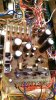
I've done some work on the power supply assembly. I replaced the two zener diodes. I decided to change all the transistors since I was putting new heatsink compound on Q1, Q2, Q8 and Q9 and I was changing Q5 and Q7 anyway. I've replaced all the electrolytic capacitors, except C18 which didn't turn up in the order. You can see it's missing in the picture. So I've got to wait before I can test it. Also managed to break the second wire on pin 10. It's really awkward to get access to the back of the board. I think I can just strip the wire back a little bit and solder it back on. I'm thinking about changing the 4 big diodes, but they tested okay so not sure if it's worth it.IMAG1017.jpg
 
Back
Top Bottom