• The move to the new server is done. There are some software and database maintenance updates in process. This has us passing the hat around to help out. We appreciate any donations. Seriously, even a dollar helps. The payment page may be found here - https://www.audiokarma.org/support.html

SX990 amp on board output caps

Wow, a thanks to me with MarkTheFixer...I'm honored. Mark's the expert. I'm just a lucky hack with a solder gun and enough knowlege to be dangerous.

Mark's concern is that there are known mistakes in schematics and board markings. I don't know for sure if the SX-990 schematic has any errors or product changes. The extra caps in your unit are puzzling.

Since you mention that this is headed for TT use and you may need more parts, did you do anything to the phono pre-amp section? Recapping and retransistoring that may be worth while.

Yes, I was concentrating on the current amp problem, but once THAT'S all spiffed up, the rest could benefit. Perhaps those parts can travel with the 2200uf caps.

Tuner alignment equipment will set you back a considerable sum. GOOD tuner alignment will make that look like pocket change. Improvised stuff will require a great deal of technical acumen.
 
Last edited:
STV-3 test results:

9V battery (8.56V actual)
1500ohms (1464 actual)

Diode #1
8.55V
1.642V

Diode #2
8.55V
1.636V

Does this confirm both parts are good to go? :thumbsdn: :thmbsp:
 
Yes, I was concentrating on the current amp problem, but once THAT'S all spiffed up, the rest could benefit. Perhaps those parts can travel with the 2200uf caps.

Tuner alignment equipment will set you back a considerable sum. GOOD tuner alignment will make that look like pocket change. Improvised stuff will require a great deal of technical acumen.

Yes...spiffed up amp card biased and tested first...then I can evaluate the rest..
All resistors left on the amp board have been tested and checked good.
I don't know what I should do about this capacitor snafu?
I could wait and install the old chassis ones with the new ones and then decide I suppose. I can always use the 1000's for something in the future..

I've been drooling over these "less expensive" Rigol scopes, DMM's and Spectrum analyzers....
Looks like for $400-$12k you could get a nice arbitrary waveform gen to do your AM/FM tests:
http://www.rigolna.com/products/waveform-generators/dg1000/dg1022/
Even that is more than I could really afford personally especially for the occasional receiver tuner restore/repair.
So I suppose used vintage or maybe repairing a more expensive broken one might be better and more fun...but then if you want it calibrated that would be $200 right there!...so inexpensive is all relative I guess...

I know new isn't the "vintage way" even with scopes, meters and the sort these days, but I really do like these newer digital instruments.
I've read some good reviews about the Rigol....very positive but never used any myself.
I enjoy watching this guy on Youtube...I just like his attitude and demeanor and I would like his lab and workbench.
http://www.youtube.com/user/TheSignalPathBlog
Fluke & Tektronix are the big names out here in the PNW but the outsourcing of American manufacturing continues....
 
well as they raise the standard of living at wherever they are manufacturing (just by being a source of increased wages from whatever HAD been the normal there), whadda know, the workers want MORE MONEY - they figure out they're being exploited, maybe they're tired of dirt floors... - so in the longer term it's gonna come back and bite the outsourcers. I went through 2 failed early can openers, so I ended up getting a particular American Made can opener, and it's already done better and longer than the (cheap, big box) imported stuff.

I've had thoughts about low distortion oscillators, A ramsey stereo transmitter and a good controllable RF attenuator. But that will end up costing at least as much as an ST 1000a on ePrey.
 
Last edited:
well as they raise the standard of living at wherever they are manufacturing (just by being a source of increased wages from whatever HAD been the normal there), whadda know, the workers want MORE MONEY - they figure out they're being exploited, maybe they're tired of dirt floors... - so in the longer term it's gonna come back and bite the outsourcers. I went through 2 failed early can openers, so I ended up getting a particular American Made can opener, and it's already done better and longer than the (cheap, big box) imported stuff.

I've had thoughts about low distortion oscillators, A ramsey stereo transmitter and a good controllable RF attenuator. But that will end up costing at least as much as an ST 1000a on ePrey.

That's exactly what will happen!...maybe by then the kids here will be ready to start all over at the bottom....being out of the work game (for now) all I'm concerned with is my health!....and there's a lot of us getting there!...LOL...I still use a hand crank can opener....no electricity involved!....hehe
I sometimes worry about the biomed equipment I been seeing...man..checking the stickers..."made in (fill in country of choice here)"....hmmm where's that?
 
I did not have any additional caps mounted on the chassis by amp board on the SX990 I re-capped. Never even saw them in the schematics.

Good luck with your 990. I copied and pasted onto Word an adjustment proceedure a while back from here at AK into my books for an easier future find. Thought you might need when you are ready.
 

Attachments

Last edited:
I did not have any additional caps mounted on the chassis by amp board on the SX990 I re-capped. Never even saw them in the schematics.

Good luck with your 990. I copied and pasted onto Word an adjustment proceedure a while back from here at AK into my books for an easier future find. Thought you might need when you are ready.

Thanks so much for that doc dnpainting, that seems pretty straightforward.
There are 2 test points on my circuit card that had wires soldered to them and hanging off the board.....I know another weird item huh...!??
TP1 is at the junction of R33 (.5ohm 2W) and the emitter of Q11 (2SC793) and TP2 is at the junction of R34 and the emitter of Q12.
I was wondering if these were potential locations for taking meter readings while doing adjustments. I have found nothing on using these anywhere and they are also not shown on the schematic, but are shown on the board layout drawing.

I found this on AK yesterday that seems to be the current values/calculations that might go with your procedure doc...!?

Out of curiosity did you install only one 1000uF/35V cap "on board" for each channel output of your model?

The second 1000uF/35V caps C15 and C16 show up on all model schematics except the "NBW" model block diagram which has the W23-006 main amp circuit board.
The one I have here is the FVW model with W15-060 amp board.
Maybe that's the explanation?
All I know is this receiver has two external chassis mounted caps 1000uF/35V in parallel with each 1000uF/35V "on board" and they show up on the block diagram for those models...
SO now I am considering 2200uF/35V on each channel "on board"...or I could mount them in the chassis clips of C15/16 and hard wire them over to the board.....:scratch2:
 

Attachments

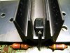
OK...so here is my closeup pictures of the STV-3 mounting at the heatsink.

Now...when I took these off there was a small amount of clear hard glue all pretty crusty and crumbling so the diodes were essentially loose and weren't really being held in place. This may have been the same material they used on the old mica washers...I don't know.
They were mostly held in place by the soldered leads to the board.
Each leg has a small piece of tubing around it to prevent any shorting to the heatsink as it passes through the heatsink and then the same on the outside leg to protect it at the heatsink edge.

What I would like to understand, improve on or accomplish is this:

These are epoxy/plastic cases with 3 flat surfaces (top/bottom/right side). Only 2 surfaces can be fitted against the surfaces of the heatsink.

Do these actually need to make positive contact with the heatsink?...or can they just float in space in there?
Do they need some sort of proper thermal contact application or would a simple dab of silicone glue do?
I would think using epoxy would be a really bad idea....
I assume something like a TO-92 heatsink tab would also be a bad thing to try and use...looking for some thoughts?

BTW I have 3 good 2SC793's as well as the rest of those old transistors...are they of any value?
 

Attachments

  • IMG_2470.jpg
    IMG_2470.jpg
    59.1 KB · Views: 49
  • IMG_2471.jpg
    IMG_2471.jpg
    61.7 KB · Views: 44
  • IMG_2472.jpg
    IMG_2472.jpg
    32.6 KB · Views: 44
voltage to ground at those wires will give you the idle current expressed as a voltage across the emitter resistance. 20 millivolts across 0.5 ohms is 40 milliamps.

this is the idle current of the output drivers, and it is the point where the amp will transition from class a operation to class b (push pull) operation.

the idle current increases from zero, and the crossover distortion drops, until a "knee" is reached where distortion does not decrease with corresponding idle current increases. this only results in extra heat dissipation in the output drivers.

vr3 and vr4 are adjusted for 20 millivolts and this is the recognized procedure. as evidenced by many many other later Pioneer manuals.

edit:

the clear stuff is glue and should be replaced with thermal transfer compound. One surface contact is ok, use the leads for some tension, it's a bit older and it's been a while since I had to deal with one, although I do have two on the shelf. It's reading heat, not pumping it out.
 
Last edited:
voltage to ground at those wires will give you the idle current expressed as a voltage across the emitter resistance. 20 millivolts across 0.5 ohms is 40 milliamps.

this is the idle current of the output drivers, and it is the point where the amp will transition from class a operation to class b (push pull) operation.

the idle current increases from zero, and the crossover distortion drops, until a "knee" is reached where distortion does not decrease with corresponding idle current increases. this only results in extra heat dissipation in the output drivers.

vr3 and vr4 are adjusted for 20 millivolts and this is the recognized procedure. as evidenced by many many other later Pioneer manuals.

edit:

the clear stuff is glue and should be replaced with thermal transfer compound. One surface contact is ok, use the leads for some tension, it's a bit older and it's been a while since I had to deal with one, although I do have two on the shelf. It's reading heat, not pumping it out.

OK I think I understand that and the TP use then. So there is a kind of diminishing return on this distortion drop beyond a certain idle current value...so 40mA is a nice nominal value with good crossover distortion and adequate idle current. Which also gives you nominal heat dissipation of the transistors?

Were any of these transistors I ordered supposed to be matched pairs?
I hope not!

I will certainly revisit this topic before firing anything up in more detail and confidence boosting.
I think I'm getting it...and thank you for these explanations...I hope I'm not jumping to any conclusions so please feel free to correct me if I say something stupid or misunderstand...
I do have a question: with these MJ21194G transistors along with the other ones KSA1013YBU, KSC1845FTA and KSC2383YTA, I noticed these are more "substantial" than the originals...so is there a more aggressive value setting that's possible with these "beefier" components?
Not that I would necessarily want to go there...I'm sure there are plenty of things that could go wrong, just curious.
This all feels a little like "overclocking" that 4.3Ghz CPU with nitrogen cooling....LOL

The thermal paste/grease under the bottom surface should be fairly easy to accomplish and then press them down tight while soldering the leads with a little tension.
I realized after I typed some of that...it's a thermal sensor not something that generates any heat....hehe
Thanks for all the help and chat!
 
no matched pairs. with an amp with an output capacitor it just plain AIN'T in the equations, literally.

beefier components = longer (cooler) life (loafing rather than straining), NOT more power - power's determined by the design, starting at the power supply. where the "limit" is clipping - that's when the tops of the waveforms are chopped off because more voltage (at that current... i.e. POWER) is NOT available.

NOT diminishing return, it just plain FREEZES...

wanna know the difference between a high buck pure class A amplifier and these A-B's? "idle" current. Lets say the class A can deliver 3 amps of current out... that means the current through the class A outputs at idle is 3 amps.... and they have to dissipate any difference between the power going to the speaker and the "idle" current power as pure heat.
 
Last edited:
no matched pairs. with an amp with an output capacitor it just plain AIN'T in the equations, literally.

beefier components = longer (cooler) life (loafing rather than straining), NOT more power - power's determined by the design, starting at the power supply. where the "limit" is clipping - that's when the tops of the waveforms are chopped off because more voltage (at that current... i.e. POWER) is NOT available.

NOT diminishing return, it just plain FREEZES...

wanna know the difference between a high buck pure class A amplifier and these A-B's? "idle" current. Lets say the class A can deliver 3 amps of current out... that means the current through the class A outputs at idle is 3 amps.... and they have to dissipate any difference between the power going to the speaker and the "idle" current power as pure heat.

I think I got that...power output is just what the system design will do before clipping. It is what it is and when you get it there that's where you want it!....your done!
Having the beefier components just provides good stability and cooler operation.

The crossover distortion is that transition point where they're switching and when everything is set correctly there is little or no switching offset??

If there is excessive offset (crossover distortion) will that manifest itself as audio distortion??
And again this is a set it and that's it. It will be as good as you can get it...right?
Is that something you can watch on a scope or fine tune?

I was looking at the schematic again and so the 50ohm trimpot and STV-3 are there to set the 2 bases of that NPN/PNP pair (2SC497/2SA497) and as the temperature starts to go up the STV-3 changes to allow a little more current???....or is it allowing less current?
And the 30k (50K now) trimpot adjusts the voltage and therefore current at those output transistors to be balanced equally??
I notice you want that center point to be 28V or half the supply voltage.
And the push-pull (Class A-B) is those two providing the + region of the waveform (push?) and the other is providing the - (pull?)

I had read that Class A is "always on" so that's why it is less attractive in terms of efficiency?
But they are more linear and you don't have that crossover distortion problem switching on and off.....correct?
Sort of like switching power supplies and linear ones....we are being driven by "efficiency" rather than quality and linearity.
I think this concept is becoming ever more prevalent today...more than we realize...
I like effeiciency but what we need is good consistent cheap power..!!:banana:
 
Thanks so much for that doc dnpainting, that seems pretty straightforward.
There are 2 test points on my circuit card that had wires soldered to them and hanging off the board.....I know another weird item huh...!??
TP1 is at the junction of R33 (.5ohm 2W) and the emitter of Q11 (2SC793) and TP2 is at the junction of R34 and the emitter of Q12.
I was wondering if these were potential locations for taking meter readings while doing adjustments. I have found nothing on using these anywhere and they are also not shown on the schematic, but are shown on the board layout drawing.

I found this on AK yesterday that seems to be the current values/calculations that might go with your procedure doc...!?

Out of curiosity did you install only one 1000uF/35V cap "on board" for each channel output of your model?

The second 1000uF/35V caps C15 and C16 show up on all model schematics except the "NBW" model block diagram which has the W23-006 main amp circuit board.
The one I have here is the FVW model with W15-060 amp board.
Maybe that's the explanation?
All I know is this receiver has two external chassis mounted caps 1000uF/35V in parallel with each 1000uF/35V "on board" and they show up on the block diagram for those models...
SO now I am considering 2200uF/35V on each channel "on board"...or I could mount them in the chassis clips of C15/16 and hard wire them over to the board.....:scratch2:

I to have those wires, I don't recall if I used those or not. I only installed the 2 caps (1000/35). Here are a couple pics of the rebuilt amp board.

attachment.php


attachment.php


I should have but did not replace the adjustment pots.
 
I think I'll just leave those wires off.
I was thinking replacing them with a simple test post, but it's very close quarters in that area.
I plan on doing the adjustment procedure per your instruction doc with the ammeter at the fuse and check all the voltages around the circuit.
Looks like you replaced one of your trimpots!

I did find there were 6 versions of this receiver made.
FSAW, FVW, FVSW, KCW, KUW and NBW. There is a round label on the back of the receiver. (See attached)
The one I have here (FVW) has the double 1000uF/35V.
Two on the board and two chassis mount and a 3300uF/80V main cap. Other versions used 2200uF/80V for the main cap...another difference.
There were also different power transformers used as well as a different main amp board on the NBW version and different FM boards..
So I think this is where the different schematics and different configurations came from.
 

Attachments

  • IMG_2482.jpg
    IMG_2482.jpg
    81.2 KB · Views: 37
doc's method leaves you guessing about the idle current and how mush is being drawn by other stages, and the voltage measurement at the emitter resistor is how Pioneer DOCUMENTS the procedure in later model's service manuals when they stopped assuming the person reading the service manual knew all about the adjustment.
 
doc's method leaves you guessing about the idle current and how mush is being drawn by other stages, and the voltage measurement at the emitter resistor is how Pioneer DOCUMENTS the procedure in later model's service manuals when they stopped assuming the person reading the service manual knew all about the adjustment.

Is there a link to that Pioneer document??
I'm all about doing things the Pioneer way!
 
Is there a link to that Pioneer document??
I'm all about doing things the Pioneer way!

doc's method leaves you guessing about the idle current and how mush is being drawn by other stages, and the voltage measurement at the emitter resistor is how Pioneer DOCUMENTS the procedure in later model's service manuals when they stopped assuming the person reading the service manual knew all about the adjustment.

http://www.kallhovde.com/pioneer/sx-950sm.pdf

http://www.kallhovde.com/pioneer/sx-939sm.pdf

http://www.kallhovde.com/pioneer/sx-980sm.pdf

modifications to procedures: just turn the volume to zero, NO extra resistors are needed.
 
Last edited:
Thanks Mark.....
I created my own adjustment procedure with pictures and diagrams and a paragraph on the back of each one.....
I did this while watching the Seahawks kick Arizona's butt!....sorry AZ....that was a blood bath!

If you might be so kind and if you have the time and inkling...would you review my steps and check for any errors or disinformation I may have included.
I thought if this is reviewed by an expert and corrected it could be posted for future noobs and knob twiddler's like myself for reference and maybe someone can make it a .pdf.
:music:
 

Attachments

Back
Top Bottom