• The move to the new server is done. There are some software and database maintenance updates in process. This has us passing the hat around to help out. We appreciate any donations. Seriously, even a dollar helps. The payment page may be found here - https://www.audiokarma.org/support.html

Taking on the big dog - Recapping my new SX-1980

Well, those numbers warm this old warrior's heart, I was going to post that without numbers, sound could be there while somethin was chewin on it's innards...

Could you post a flatter close up of the resistors on the back of the board, and if the picture is darker rather than washed out by brightness I can tease out more details.

Seems like right now a kludge for those current sources (q206, q207) is installed. And unless contradicted by a documented factory service bulletin, I don't think those resistors are a good idea.

I'd offer you a pair of the EchoWars current regulators at cost, but I'm down on extras right now.

OH, and ALL the TO-220's on the power supply board should be changed over to mje15032/33's. Get new mica's for the two that are insulated just in case.

That -80v regulator with the blackened METAL tab is a sure sign of overheating... just about ANY shiny metal on transistors that has blackened is a sign of long term (over) heat.
 
MTF-
Thanks for looking over my shoulder on this. I didn't want to give anyone cardiac stress - least of all me.
I don't think any of the transistors are darkened. The Mitsubishi transistors appear to have a black oxide coating on the tabs whereas that upper (in the picture) 2SC3890 has a non-metallic (black) surface on the exposed surface of the tab.

I have seen some discussion of EW's current source but I'm not certain on how it is installed. Is this something I could easily create?
Is it really necessary to replace the 80v regulators with the OnSemi parts if the current parts are functioning?

I doubt if I'll ever be stressing this receiver. I think my ownership of this is akin to the guy in NYC who owns the Corvette and once in a while takes it out to the FDR drive and races it up to 45 mph.

Does it make sense to install a small fan to cool the PS PCB? There's some space forward of the board where it could be installed.

JimB
 
Last edited:
The amp PCBs

The amp boards - these were pretty easy. Each had 3 caps for a total of 6.
I replaced the little blue 0.22uf cap with a poly film cap.

4 - 100uf/100v
2 - 0.22/25v

Before reinstallation I also cleaned the oxidation off of the connector pins with a bit of emery paper to make them nice and shiny.

And here are the before and afters...


attachment.php


attachment.php
 

Attachments

  • P2141182.jpg
    P2141182.jpg
    110.8 KB · Views: 482
  • P2141183.jpg
    P2141183.jpg
    108.3 KB · Views: 483
It's tuner Tuesday!

Recapped the tuner over the last few days.
This one's a real challenge since it can't easily be removed from the chassis due to all of the attached wires. I opted to do it in place which meant having to solder at a distance within the chassis.
It is at least a pleasure working on a clean unit - I've done zero cleaning so far!
The tuner had 14 of those nasty little blue tantalum capacitors which I replaced with the poly film caps for values of 1.0uf or less and electrolytics for values above that.

Best news is that everything still works. Now it's time to pull off the faceplate and get to the front mounted PCBs.

Here's our list:

Tantalum(CSZA) - replace with poly film (1.0uf or less) or electrolytic:
4 - 0.1uf/35v
1 - 0.22uf/35v
1 - 0.47uf/35v
2 - 0.56uf/35v
3 - 1.0uf/25v
1 - 2.2uf/16v
1 - 4.7uf/16v
1 - 6.8uf/6.3v

LR - Low leakage (orange CEANL):
2 - 33uf/25v
4 - 10uf/16v

Electrolytics (CEA):
3 - 1.0uf/50v
1 - 2.2uf/50v
1 - 3.3uf/50v
1 - 4.7uf/35v
7 - 10uf/16v
2 - 22uf/16v
1 - 33uf/50v
2 - 47uf/10v
1 - 100uf/6v
6 - 100uf/16v
1 - 220uf/16v

And the photo's, the first is the before and then the after...


BEFORE...
attachment.php


AFTER...
attachment.php
 

Attachments

  • P2151185.jpg
    P2151185.jpg
    98.8 KB · Views: 42
  • P2151186.jpg
    P2151186.jpg
    116.8 KB · Views: 421
  • P2141184.jpg
    P2141184.jpg
    116.5 KB · Views: 430
I'm beginning to hear the sound at the end of the tunnel ♫♫!
Pulled off the faceplate and scrubbed / soaked the knobs (which were pretty clean).

Recapped the Tone Control Assembly and the Flat Amplifier (and volume) Assembly.

Capacitor list.
Tone Control Assembly:
12 - 2.2uf/50v (Low Leakage orange / CERB)
4 - 100uf/16v (light yellow / CELL)
4 - 100uf/10v (light yellow / CELL)
2 - 10uf/25v tantalum (replace with electrolytics)
4 - 4.7uf/25v tantalum (replace with electrolytics)

Flat Amplifier (and volume) Assembly:
2 - 330uf/35v "SL"
2 - 4.7uf/50v "LR" low leakage
4 - 10uf/16v "SL"

Eye candy...

Tone control assembly BEFORE...

attachment.php


Tone control assembly AFTER...

attachment.php


Flat Amplifier Assembly BEFORE...

attachment.php


Flat Amplifier Assembly AFTER...

attachment.php
 

Attachments

  • P2151187.jpg
    P2151187.jpg
    137 KB · Views: 409
  • P2151184.jpg
    P2151184.jpg
    142.9 KB · Views: 408
  • P2151186.jpg
    P2151186.jpg
    109 KB · Views: 405
  • P2151185.jpg
    P2151185.jpg
    121.9 KB · Views: 407
Last edited:
w1jim....that is great work....and cool photos.......keep'em comin'!

The 1980 has been eluding me for some time..................yours looks great.
 
Closing in on the music!

Recapped the Filter Switch PCB (AWM-119) and APC Assembly (AWX-124) tonight.
Next up will be the LEDs for the indicator lights. I'm planning on leaving the dial lamps the standard incandescent bulbs - I like the warmth.

Filter Switch PCB (AWM-119) Caps:
All tantalums. The 0.22 values replaced with poly metal film caps, the others are changed to electrolytics:

4 - 0.22uf/25v
2 - 10uf/25v
2 - 4.7uf/25v


APC Assembly (AWX-124) Caps:

1 - 2.2uf/25v (was a tantalum - replaced with an electrolytic)
1 - 47uf/16v
1 - 100uf/6.3v
1 - 100uf/16v


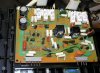
Filter Board BEFORE...

attachment.php


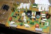
Filter board AFTER...

attachment.php


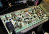
APC BEFORE...

attachment.php


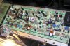
APC AFTER...
attachment.php
 

Attachments

  • P2161192.jpg
    P2161192.jpg
    147.9 KB · Views: 344
  • P2161190.jpg
    P2161190.jpg
    115.1 KB · Views: 341
  • P2161189.jpg
    P2161189.jpg
    126 KB · Views: 340
  • P2161188.jpg
    P2161188.jpg
    122.5 KB · Views: 455
Last edited:
I am getting ready to take on this job. But I will go a few steps further. I know the old TO-3's are the original. I will replace them. Anything that looks remotely close to being bad will be replaced. I did see a couple of resistors that looked a little baked. So everything around them will be replaced. What I am getting ready to do is going to be very expensive. My 1980 will be like new or better then new. I just done a Kenwood KR9940. The cost on parts alone was 600.00+. Everything that was on the boards was replaced and I dont think it ever sounded this good. It was only 5 years old when I got it and it sounded good...but not this good. So I may go this route on the 1980.
 
+1 :thmbsp: Nice work Jim. Silly question, but is there an advantage to replacing tantalum caps with electrolytic?
The tantalum where thought to be the hot setup in their day but history has shown that they tend to sound a bit harsh and that when they fail they do so catastrophically - often augmented by a puff of smoke and pretty flames.
Electrolytics on the other hand just tend to drift in value as they age.

They don't like reverse voltage much either..

cap1.jpg
 
Last edited:
I am getting ready to take on this job. But I will go a few steps further. I know the old TO-3's are the original. I will replace them. Anything that looks remotely close to being bad will be replaced.
Replacing the output transistors would be (IMHO) I'll advised. If they work and measure properly when/if you test them I'd leave them alone because they are unobtanium. Even when you could get them from Pioneer they listed at ~$50 each. Also these are not in standard T0-3 packages.
You might consider refreshing the thermal grease on them if they've gotten extensive temperature cycled through the decades.
I'd review the following thread before proceeding:
http://audiokarma.org/forums/showthread.php?t=60536

That would be an interesting exercise in OCD behavior to replace the other components. On the power supply board (which experiences most of the heat damage) that might be a good thing but be advised that the FET transistors are not readily available. Apparently the same part number were available in 30 and 50 volt ratings. You'll need the 50 volt ratings but there is no way to determine which you'll get. That is why Echowars devised a simple "current source" device to replace them. IMHO if they work just leave them. Replacing the other transistors, caps and resistors would be OK but proceed with caution as that PCB has very frail traces and you could easily damage them just by looking at them.
You could also have a new board made but that would be a significant undertaking!
Replace the 35 volt zener diodes with a pair of 17v and 18v 1/2 watt zeners in series - apparently that addresses a known frailty in that area.

It is likely that the tuner, tone, filter and APC boards will not have experienced any heat damage so I wouldn't go crazy there. Just focus on replacing the parts on the amp board. And replacing the adjustment pots on these boards with multi-turn trim pots would be a good thing.

I've thought about replacing all of the resistors in the phono stage with precision metal film resistors which are said to be quieter then the carbon film parts but want to listen to it first. There are some select metal film resistors in the phono stage so this might have been addressed by Pioneer originally so this may not be necessary in the long run.

That Kenwood sounds nice, I did an extensive rebuild on a KR-9600 a few years ago; recap, binding posts, LEDs and upgraded opamp in the FM section - a real keeper!

JimB

JimB
 
I was afraid of this.....

Well, it's his 1980 to wreck.

Like Dirty Harry Callahan said: "A man's got to know his limitations"

Go ahead, replace ALL the TO-3's in the 1980 - THAT's safe enough.....
(there ain't any...)


Advance warning, I charge a HELL of a lot more to UNSCRAMBLE MESSES. Because it TAKES a hell of a lot longer. And it AIN'T a labor of love like a restoration where I end up undervaluing my time, but rather a horror show as I try figure out what's wrong and how to set things right
 
Last edited:
W1jim- you listed here:
APC Assembly (AWX-124) Caps:

1 - 2.2uf/25v tantalum
You replaced this with a tantalum or was that what was in there? Thanks
I ask cause it looks like you have been replacing those but in your replacement list it looks as you installed one so I wondered why you would use one there.
 
W1jim- you listed here:
APC Assembly (AWX-124) Caps:
1 - 2.2uf/25v tantalum
You replaced this with a tantalum or was that what was in there? Thanks
I ask cause it looks like you have been replacing those but in your replacement list it looks as you installed one so I wondered why you would use one there.
Sorry, a lack of consistency in my nomenclature here.
This was a tantalum replaced with an electrolytic - the "after" photo shows this.
I've added a clarification to the original post.
 
Back
Top Bottom