

You are using an out of date browser. It may not display this or other websites correctly.
You should upgrade or use an alternative browser.
You should upgrade or use an alternative browser.
Tantalums in the signal path?
- Thread starter Sergimm
- Start date



gslikker
Super Member
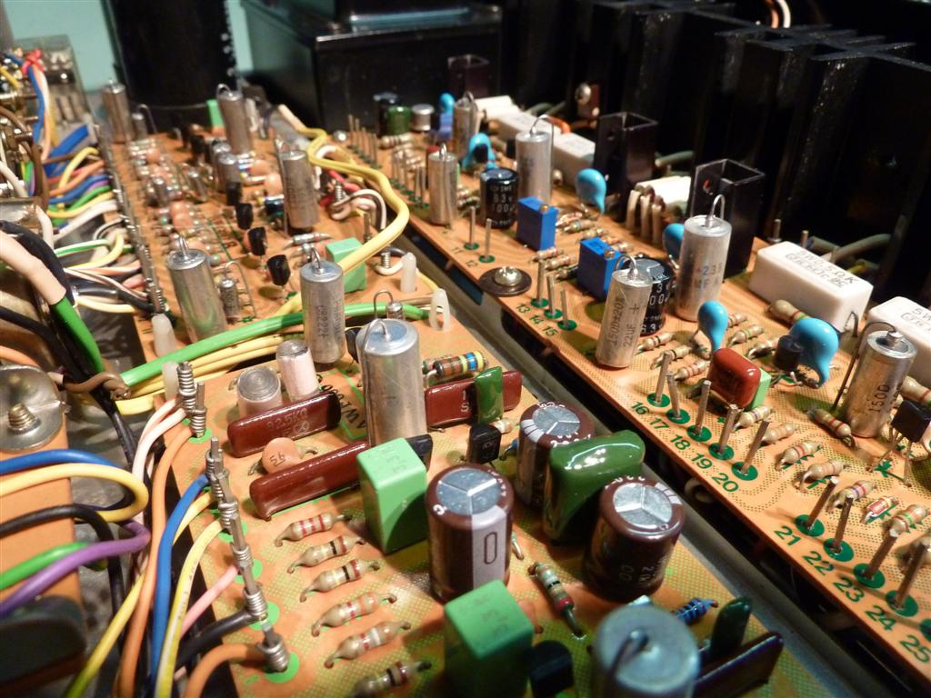
Those sizes are simply called A,B,C and D and very standardized for all manufacturers small general purpose solid tantalum caps.Nice,clean work on the Pioneer ! I haven't seen tantalum capacitors that big before.
The ones I've seen are very small like teardrops or small egg shapes with both leads radial.
I think the most well known common old type is Sprague 150D so if you look it up on the search engine you will find all about it.

elnaldo
Lunatic Member
( a bit OT, I have to mention that many people "upgrade" their preamps replacing electrolitic capacitors with tantalum caps, some people sell this also as a service, upgrading to tantalum caps, and that some of the very famous (and expensive) Neve preamplifiers used in the larger recording studios around the world are plenty of tantalum capacitors inside. I don't have the circuits at hand to check the specific application, buy it's worth to mention that many people believe that the tantalum caps are part of the sonic signature of those well regarded preamps. )


Sergimm
Active Member
Haha yes, I see. I appreciate all the answers though! I learned a lot, I love this place.Like I said Sergimm, never ending discussion
Have you tried something yet?
In the end I went for WIMAs MKS2, they seem to work well. An interesting fact was that each of the ten 3.3uF WIMAs I had tested around 3.0uF, which is right at the 10% tolerance limit specified. Given that all the caps gave similar measurements, it seems like is by design. Anybody else found something similar?
Also, at some point somebody mentioned that you can test how some tantalums are prone to distortion or interference just by putting a finger close to the cap. In my case there is the same amount of “noise” when doing that regardless of having the tantalum or the film cap. Was that just BS?

Sergimm
Active Member
Not 100%. I am using a multimeter and a cheap transistor tester, and they more or less agree.Do you know that your test equipment is correct? My multimeter has a capacitance tester that I checked with many values of 2% capacitors and appeared to be consistent but it could still be off at certain values.
That has to do with the "outside foil" lead where if it is in the "positive" position it is prone to picking up noise. Yes, film caps by nature are bi-polar, BUT one lead is the outside foil and should be put in the negative side so the "antenna" is less prone to picking up noise. Caps used to be marked which lead is the outside foil side from the tube days. But many still have the "stripe", but aren't necessarily the outside lead anymore. You need to "test" for that. One way is a setup with a scope to look for the noise that comes from merely handling the cap. The scope will pick up more of the noise if the outside foil lead is on the positive probe. Reversing the leads will show either less noise, or more noise and will indicate which cap lead is the outside. Lesser noise will be the "negative" lead. Negative (outside foil) always points toward the source in the circuit, or the "ground" with bi-polar caps.Haha yes, I see. I appreciate all the answers though! I learned a lot, I love this place.
In the end I went for WIMAs MKS2, they seem to work well. An interesting fact was that each of the ten 3.3uF WIMAs I had tested around 3.0uF, which is right at the 10% tolerance limit specified. Given that all the caps gave similar measurements, it seems like is by design. Anybody else found something similar?
Also, at some point somebody mentioned that you can test how some tantalums are prone to distortion or interference just by putting a finger close to the cap. In my case there is the same amount of “noise” when doing that regardless of having the tantalum or the film cap. Was that just BS?
Sergimm
Active Member
You are blowing my mind right now. I’ve installed countless bipolar capacitors without knowing this and I’m wondering how much interference I’ve added to the systems. Does this apply to all bipolar capacitors, or only the coupling ones? I’ve found this video that looks like a good primer on the subject, can’t wait to watch it.That has to do with the "outside foil" lead where if it is in the "positive" position it is prone to picking up noise. Yes, film caps by nature are bi-polar, BUT one lead is the outside foil and should be put in the negative side so the "antenna" is less prone to picking up noise. Caps used to be marked which lead is the outside foil side from the tube days. But many still have the "stripe", but aren't necessarily the outside lead anymore. You need to "test" for that. One way is a setup with a scope to look for the noise that comes from merely handling the cap. The scope will pick up more of the noise if the outside foil lead is on the positive probe. Reversing the leads will show either less noise, or more noise and will indicate which cap lead is the outside. Lesser noise will be the "negative" lead. Negative (outside foil) always points toward the source in the circuit, or the "ground" with bi-polar caps.
Mr. Carlson's Lab is an excellent channel. He does explain it very well.You are blowing my mind right now. I’ve installed countless bipolar capacitors without knowing this and I’m wondering how much interference I’ve added to the systems. Does this apply to all bipolar capacitors, or only the coupling ones? I’ve found this video that looks like a good primer on the subject, can’t wait to watch it.

Most of the time in SS gear, it's not an issue at all, but you do occasionally come across instances like this one, especially in sensitive locations. With electrolytic bi-polar caps, the short lead is the outside foil lead just like it is the negative lead in polarized caps.If it makes you feel any better, Sergei, I have stopped bothering with the leads. I did so at the beginning but it took too much time, so I just plonk them in so I can read the values. I really haven't had any issues with noise pickup before or since.

PabloTincho
Super Member
I just got a Superphon DM-200, for $120 plus shipping, yes sounds really good, and is working fine, maybe pushing 25 years.It’s probably just shy of 35 years ago that I asked the same question of Stan Warren (cofounder of PS Audio) as the Consumer Electronics Show in Las Vegas. Stan has a reputation for being a purist and minimalist who selects the components he uses through double-blind listening tests. I was a newly degreed EE at the time -- and was trying to learn from one of the gurus. We had met previously as PS Audio used to be in my college town of San Luis Obispo CA.
Stan and I were discussing the design aspects of his new Superphon DM-200 power amplifier (which I ended up purchasing from him at the show). The DM-200 was one of his products which used tantalum capacitors throughout the signal path. It and his "Revelation" preamps were very highly regarded "budget" preamps at the time (and may well still be).
Stan explained at the time that from his experimentation, solid dielectric capacitors (tantalum, silver mica) consistently provided better sonic performance when used in the signal path. I recall his comment that the capacitors in his designs remain powered up at all times and are biased in the middle of their operating voltage range. He found that keeping the capacitors charged provided both the best sound and greatest longevity. (I'm not sure if the front end of the power amplifier remains at idle -- probably not.)
Not sure what the current thinking is in this regard but those tantalum capacitors may have been very carefully considered by the designer. If you're changing out the capacitors you might want to carefully evaluate the before and after sonics.
Since I like it so much, I am going to send it to my tech for a full restoration, to keep the sonic signature just change the capacitors ? leave the tantalum and silver mica alone ?