• Please note that Audiokarma will be offline briefly for updates early on Monday morning, September 28th.

Technics RS-1500 FF and REW do not stop

OK, so now I see that I made a mistake on assuming wiring to Connector B.
It looks like the two 6 pin connectors on the Key Switch board are wired not to Connector B, but to the two large white connectors.
The board traces then go to Connector B.
Can you easily get to the two 6 pin connectors on the board, or is it easier to get to B on the board?

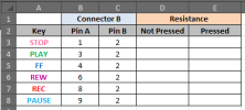
If you can get to B then with power off, measure resistance first with key not pressed, then pressed.
1789752258600.png
1789750980378.png
 
Last edited:
Where do they plug in, both only have 6 pins each.

I was reading another post on tapeheads and the suggestion for transport problems was to replace the 9 electrolytic caps on the Main Control board. You could start with that and see if it helps.

View attachment 3839074
The two large white rectangles each side of contact B are the plugin points. I have already replaced all the electrolytic caps (around 140).
The FF and REW problem was there before the caps change.
 
OK, so now I see that I made a mistake on assuming wiring to Connector B.
It looks like the two 6 pin connectors on the Key Switch board are wired not to Connector B, but to the two large white connectors.
The board traces then go to Connector B.
Can you easily get to the two 6 pin connectors on the board, or is it easier to get to B on the board?

If you can get to B then with power off, measure resistance first with key not pressed, then pressed.

View attachment 3839128
View attachment 3839118
If i understand you correctly, I should measure the B contacts with pin 2 as ground.
1 to 2 unpressed= 1ohm. Pressed= 0,2ohm.
3 to 2 unpressed= 0,2ohm Pressed= 1Kohm
4 to 2 unpressed= 1Kohm Pressed= 1Kohm
6 to 2 unpressed= 1Kohm Pressed= 1Kohm
8 to 2 unpressed= 1Kohm Pressed=1Kohm
9 to 2 unpressed= 1,6 Kohm Pressed=1,3 Kohm
I also checked continuity of the colored lines between left and right sockets to B. All "beeped" OK.
 
OK, so now I see that I made a mistake on assuming wiring to Connector B.
It looks like the two 6 pin connectors on the Key Switch board are wired not to Connector B, but to the two large white connectors.
The board traces then go to Connector B.
Can you easily get to the two 6 pin connectors on the board, or is it easier to get to B on the board?

If you can get to B then with power off, measure resistance first with key not pressed, then pressed.

View attachment 3839128
View attachment 3839118
Have you given up on me?
 
No, but I've been busy trying to help other AK'ers find their problems.
I'm still not sure that we got good measurements of the keypad switches.
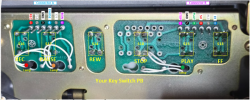
It took me a while to figure this out, but here is a photo of your keypad that you provided.
Am I correct that there are no wires going from Connector A and B to the Main board if you remove any cables?
OK, here is the test:
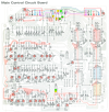
  1. I matched up the two connectors that I arbitrarily labeled Connector A and B between the schematic and board layout.
  2. I annotated your photo with the keys and matched it up with the Main Control board two connectors.
  3. Each key is normally open when not pressed and should be grounded when pressed and held down.
  4. We should test each key to make sure they are not stuck in the pressed position.
  5. Disconnect the two cables that go to the board.
  6. Set your DMM to measure Ohms.
  7. The REC button is wired different than the others. We'll test that first.
  8. On Connector A, connect black lead to pin 3 GND, red lead to pin 1 REC. It should read OL.
  9. Now, hold down the PLAY button and keep it pressed while you press the REC button and it should read 0 Ohms.
  10. Keep the black lead on pin 3 and move the red lead to pin 4 PAUSE. Resistance should read OL.
  11. Report your resistance for both not pressed and pressed conditions.
  12. Press and hold the PAUSE button, the resistance should read 0 Ohms.
  13. Move the red lead to pin 6 REW, do the same test.
  14. Now we test Connector B
  15. Move the DMM black lead to the GND pin 2 on Connector B
  16. Move the red lead to pin 1 STOP, do the same test.
  17. Move the red lead to pin 3 PLAY, do the same test.
  18. Move the red lead to pin 6 FF, do the same test.
  19. Report you test results.
1790347207654.png
1790347256415.png
 
Back
Top Bottom