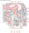
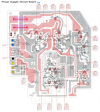
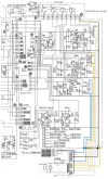
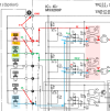
Let me understand what you are measuring:
- With power OFF, NO buttons pressed, when you measure resistance from Conn B Pin 2 to Pin 4 you get 2 Ohms (FF button)
- Same conditions as above, Conn B Pin 2 to Pin 6, you get OL (means over "Over Limit"... resistance too high to measure) = Open connection (REW button)
- Same conditions as above, Conn B Pin 2 to Pin 1, you get OL (STOP button)
If this is all correct, it means that there is a short between pins 2 and 4.
It could be on the Key Switch board or the button is stuck in the depressed position.
Between the other two tests, it reads OL because the button is not pressed so the signal path is "Open".
You can test this by measuring the resistance between Pin 2 and Pin 6 (OL), then press and hold the REW button. The reading should go to 0 Ohms.
Same with the STOP button.
View attachment 3838353
You can test the other buttons in the same way, continuity from Pin 2 to the appropriate button. Should be OL (open) when not pressed, 0Ohms when pressed.
If this is all true, then we need to figure out what is bad.
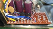
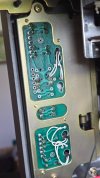
Can you post a photo of the front and back side of the Key Switch board?



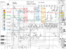
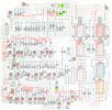

 I think I fixed them all.