• The move to the new server is done. There are some software and database maintenance updates in process. This has us passing the hat around to help out. We appreciate any donations. Seriously, even a dollar helps. The payment page may be found here - https://www.audiokarma.org/support.html

Technics SA-303 Help

OldZofTorC

AK Subscriber
Subscriber
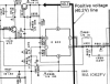
I have really believed i would figure this out but it is just kicking my ass. IC603 is aSTK1039. I have moved the two STK around and the Right channel will work with either one. I must have F601 removed to enable me to play the right channel. With the fuse in place i get noise and the Dim bulb lights up. I have undone the ribbon cable represented as 24-23-22-21-25 in circles. having done this I can leave F601 in place. Voltage measurements with this situation is (w/dim bulb) at IC603 pin 1 neg 32v, pin2 neg 34v, pin 4 pos 29v, pin 7 pos 29v, pin 9 pos 31v, pin 0 pos 30 V. I have pulled and checked c621-623-625-627.R617-619. I have taken measurements with the ICs out of circuit. Only difference between the two is .5v at 4 and 7 on the bad channel vs. .026v on the good chip. So as far as I have gotten is that it is Positive voltage that is getting into inputs. I have been on this for days and would normally have at least stumbled on to the solution.
technics sa303.png
 
Register to hide this ad
I must have F601 removed to enable me to play the right channel. With the fuse in place i get noise and the Dim bulb lights up.


Shorted out headphone jack or speaker select switch.. Ohm out the headphone jack and the speaker select switch.Also have a good look at the speaker binding posts for a stray bit of wire shorting out the binding post for the right channel.
 
Last edited:
Thank you for the response.I am not expecting you to try to figure this out for me. I am so deep into it I am bound to be close. I just lack experience. I have lifted the cable before the jack and selector switch. The problem is at the input. I dug in deep last night removing components. I am concentrating on the input at pin 0 which is at 32V (dim bulb). Also at the ribbon cable leaving the IC pin 24 has the same voltage. With the ICs out of circuit there is a difference at the ribbon cable .5v on the bad channel, .025v on the good channel.
 
Thank you for the response.I am not expecting you to try to figure this out for me. I am so deep into it I am bound to be close. I just lack experience. I have lifted the cable before the jack and selector switch. The problem is at the input. I dug in deep last night removing components. I am concentrating on the input at pin 0 which is at 32V (dim bulb). Also at the ribbon cable leaving the IC pin 24 has the same voltage. With the ICs out of circuit there is a difference at the ribbon cable .5v on the bad channel, .025v on the good channel.
:lurk:
 
The voltages at the differential amps AN7060 are good. The voltages at Q601 are all around 32V. Feeding that 32V into the STK and causing my troubles. I replaced Q601. Man I want to get this off my bench.
 
I use a desktop also, don't have a 'smartphone'.

Let us start with basics.
IC603 is removed at this time?
On DBT, what watt bulb?
Measure dcv at IC603:
Pin 9:
Pin 2:
Pin 0:
Pin 1:
Pin 7:

Measure dcv at IC601:
Pin 8:
Pin 9:
Pin 5:
Pin 4:
Pin 1:
Pin 2:
Pin 6:
 
100w dim bulb. 603 is out of the circuit. Ribbon cable to headphone jack is lifted. 680ohm resistors are in between 0-7 and 1-4.
Pin 1 19.3
Pin2 34. 5
Pin 7 25.8
Pin 9 12mv
Pin 0 32.5
IC 601
Pin 8 33V
Pin 9 33V
Pin 5 -6.9V
Pin 4 0V
Pin 1 -79mv
Pin 2 -80mv
Pin 6 31.9V

All leads on Q601 are 32V
 
Last edited:
These are IC603 pin number dc voltages?
Pin 1 19.3
Pin2 34. 5 Pin 2 is the negative supply voltage pin, should be -40.2vdc, lower on dbt
Pin 7 25.8
Pin 9 12mv Pin 9 is the positive supply voltage pin, it should be +40.2vdc, lower on dbt.
Pin 0 32.5

Is your meter black lead connected to chassis ground, and measuring with red? (I am presuming it is a DMM)
 
Well, that makes more sense now, pins 4 and 7 are halfway between 0 and 1, as i was looking for. The power supply rails are symmetrical (enough) to be comfortable with while on dbt.

Please post dcv:
For Q601:
E:
B:
C:
E to B on mV scale:

For Q603:
E:
B:
C:

Negative side of C627:
 
Q601 has 32V on all legs.
Q603 E 33 C 34.2 B 33.7 E-B .723

C627 -6V and 26v on the positive side.
 
Last edited:
Please put one probe on the emitter of Q601 and the other probe on the base of Q601, not a ground reference voltage, a measurement directly from the legs/pads voltage. I am hoping for a pn junction voltage around 0.600 vdc, but post whatever it actually is.
 
I'll be back. I have to go take care of a job before it gets too hot out.
No problem, your project, your schedule, :)
It looks like B-E of Q603 is what you reported as 0.723.
Please put one probe on the emitter of Q601 and the other probe on the base of Q601, measure dcv:
 
Back
Top Bottom