

You are using an out of date browser. It may not display this or other websites correctly.
You should upgrade or use an alternative browser.
You should upgrade or use an alternative browser.

Folkas
New Member
So, I replaced the Q401 transistor with two 2SA970 and the amp works! The sound is great. No distortion. The only thing that might be concerning is the 135 mV DC-Offset on one channel (with two 2SA970 and old STK0039), while on the other it's 22 mV.
 Since nothing is burning and the other voltages doesn't seem to be affected, maybe it is a typo then.
Thanks for the help, guys!
What kind of maintenance do you have in mind? I used some contact cleaner on the volume pot, since it was crackling a bit.sregor also gave you some good suggestions towards substitutes also. Once you have it functional you may want to do general preventative maintenance that a forty year old electronics device usually needs. Keep us posted on progress.
Well, x2 voltage is not a minor deviation.Voltages on QA503 look okay to me. Since voltages are unregulated at that point, expect minor deviations (line voltage will affect in regulated voltages) Think maybe a typo?
Since nothing is burning and the other voltages doesn't seem to be affected, maybe it is a typo then.Thanks for the help, guys!

Schmidlapper
Super Member
Electrolytics in the power supply are often replaced at a minimum, all the electrolytics replaced is not unheard of at forty years. I have done both options, depends on symptoms (hum), importance of amp or how ambitious you want to get. Checking the bias and D.C. Offset and adjusting them to spec if you can locate the correct procedures. You have high D.C. Offset on the one channel, you may be able to adjust it down. I have two amps that use a potentiometer to adjust D.C. Offset, another requires matching the transistors in the differential comparator section.

Well, x2 voltage is not a minor deviation.
Thanks for the help, guys!

"Blue" voltages from post 6 - Collector and emitter are close. Base voltage makes no sense. Other side of resistor going to base looks okay. Rest of circuit only sees Emitter voltage which looks okay to me (32.3 versus 30.5)
hi new guy here was wondering if anyone could help me ?
ive posted here has i have the same amp and Schematics are already posted here
ive replaced ic402 stk0039 has it was blown along with r436 resistor every thing is working again but im confused ,when i check voltage on q407 and q408 the voltage should be the same on collector q407 is at -5.9 which is about right but q408 is -27.3 and i cant for the life of me work out why ?
ive posted here has i have the same amp and Schematics are already posted here
ive replaced ic402 stk0039 has it was blown along with r436 resistor every thing is working again but im confused ,when i check voltage on q407 and q408 the voltage should be the same on collector q407 is at -5.9 which is about right but q408 is -27.3 and i cant for the life of me work out why ?

cilynx
New Member
Thanks to everyone on this thread, I was able to identify a bad STK-0039 and resurrect a very unhappy SU-8044. I greatly appreciate y'all documenting your adventures along the way. @mark 700 -- did you get this sorted over the last few months? If not, what are all of the readings around Q402, Q404, Q408, Q410, and IC402? I have the testpoints as well as their factory correct and actual values from my unit documented here.

Anolsos_1974
Active Member
Hello everyone,
This is my first post!
Overview - Should I investigate Q503 and/ or Q504?
I am putting together a little (franken) system. I got a Technics SU 8044K for free and was told it had a buzzing sound. I got it home and no buzzing sound, but both channels sounded 'blown' (a bit lightly farty). The speaker select felt awful (gritty). There was no difference at all when I adjusted volume, balance, tone, loudness filters etc.
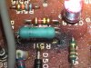
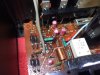
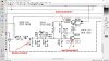
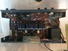
After looking at the 'deoxit' thread I followed the 'thorough' version. At first it fixed everything - and it sounded pretty nice. Then it kept alternating between good sound, then farty, then buzzing but OK sound. I then inspected the cicuit board and found a blown resistor. After reading this thread I learned that resistors don't blow on their own so I am now hunting for culprits. I attached pictures of the part schematic that relates to my problem (the full one is too large), and a close up photo of the blown resistor with brown circuit board. I *think* I am capable of checking and replacing Q503 and Q504.
My question is whether it is worth it? I don't know what this bit of circuit does so I could be walking into a mine-field. I don't mind small mine fields but I was hoping whether someone might just tell me which type I might be heading for? Thanks in advance! I have already learned so much from this website. Richard
This is my first post!
Overview - Should I investigate Q503 and/ or Q504?
I am putting together a little (franken) system. I got a Technics SU 8044K for free and was told it had a buzzing sound. I got it home and no buzzing sound, but both channels sounded 'blown' (a bit lightly farty). The speaker select felt awful (gritty). There was no difference at all when I adjusted volume, balance, tone, loudness filters etc.
After looking at the 'deoxit' thread I followed the 'thorough' version. At first it fixed everything - and it sounded pretty nice. Then it kept alternating between good sound, then farty, then buzzing but OK sound. I then inspected the cicuit board and found a blown resistor. After reading this thread I learned that resistors don't blow on their own so I am now hunting for culprits. I attached pictures of the part schematic that relates to my problem (the full one is too large), and a close up photo of the blown resistor with brown circuit board. I *think* I am capable of checking and replacing Q503 and Q504.
My question is whether it is worth it? I don't know what this bit of circuit does so I could be walking into a mine-field. I don't mind small mine fields but I was hoping whether someone might just tell me which type I might be heading for? Thanks in advance! I have already learned so much from this website. Richard
Attachments
Schmidlapper
Super Member
Have you verified the voltages shown on the schematic for D510 and then Q503 and Q504 are close to what you have?
Bill S
Bill S
Anolsos_1974
Active Member
Hi Bill, thanks for your response. I will try as you suggest, and post back...I'm presuming I power it up and attach my meter from underneath...Have you verified the voltages shown on the schematic for D510 and then Q503 and Q504 are close to what you have?
Bill S
Schmidlapper
Super Member
Yes, and the schematic should tell you in the notes any initial setup required for provided nominal values.
Anolsos_1974
Active Member
Ok, I was wrong R511 is actually fine (1500 ohm), despite the brown circuit board. So I plugged it back in and everything works now and sounds nice. I'm wondering if it might just be really dirty. Perhaps I should carry on cleaning the pots for a few days. This amp actually came with a second - Technics SU C04, it had one channel out completely and now I have got most of it back with contact spray. What do you think? Shall I continue with contact spray on the 8044 for a few days or does it need deeper diagnosis?
Schmidlapper
Super Member
Yes. Your amp is working, intermittently, but working. Intermittent problems are sometimes the hardest to diagnose, but a common cause on old equipment is dirty contacts, connections and switches, so a thorough cleaning is a great start.
Anolsos_1974
Active Member
Nice. That's what I hoped. I'll carry on with contact cleaner for a few days on both amps and see where we get to!
Anolsos_1974
Active Member
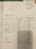
I put the multi-meter across the volume potentiometer, strangely one channel doesn't change resistance at all when I rotate the knob. Might it just need a new potentiometer?
Schmidlapper
Super Member
Are you sure you are measuring from the wiper terminal to the input terminal on the suspect pot? Check between all the leads on the pot and see if any will change. Let me know what values you get.
Anolsos_1974
Active Member
Schmidlapper
Super Member
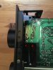
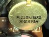
Can you provide me a close up of this pot on the schematic? I need to correlate your table with the schematic. Also a photo of the pot connections.
Anolsos_1974
Active Member
Anolsos_1974
Active Member
Schmidlapper
Super Member
Ok I've found the schematic. I wanted to make sure they weren't paralleling any resisters across the pot. The pot with terminal 1-5 looks to track continuously, The pot with terminals 2-6 sorta starts to lag and stops at 40k. Just to fill in the blanks what do you read from 3-5, and 4-6 from min to max? I know what I expect it to be.