• The move to the new server is done. There are some software and database maintenance updates in process. This has us passing the hat around to help out. We appreciate any donations. Seriously, even a dollar helps. The payment page may be found here - https://www.audiokarma.org/support.html

?Testing Transistors?

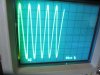
So we are still not getting signal through the 19KHz/38KHz chain. Well, dig the scope back out and look at the collector of Q402. You are looking for a 19 KHz signal/ so sweep rate 50 uS/div.

First decent looking trace I've seen.

 

Attachments

  • IMG_2839.JPG
    IMG_2839.JPG
    73.8 KB · Views: 7
That looks pretty good. Still don't know why the waveform is not covering the entire width of the display. There is the trace position adjustment, and the knob that sets the sweep rate "A & B SEC/DIV" - the larger grey knob should lock into the clear plastic underneath. Usually you just have to turn the grey knob CCW until it engages the clear plastic, and then the two will move together. That disables the delayed trace.

Put the scope on the cathodes of D401/D402. Switch to DC coupling on the Channel 1 input selector. We should have 38 KHz here, so you might want to increase the sweep rate to 20 us/div.
 
This should look like a full wave rectified signal with a frequency of 38 KHz. Amplitude depends on the turns ratio of the transformer (L405). but I would expect about 3 volts peak. If not, then use your ohmmeter to check the continuity of the secondary of L405.
 
This should look like a full wave rectified signal with a frequency of 38 KHz. Amplitude depends on the turns ratio of the transformer (L405). but I would expect about 3 volts peak. If not, then use your ohmmeter to check the continuity of the secondary of L405.

Flat line on scope.

Looks like another open coil. Seeing some resistance, about 61K on the secondary side. Not the 22 ohm or so you would expect from inductor coil. Primary side of inductor reads normal.

L405 from the parts board is open too. I'm out of spares.
 
Last edited:
Pulled L405 from parts board is open one side also, just the reverse. I'm out of parts. Sucks to get almost there and be stuck up the creek without an inductor (actually it is a transformer).

The parts store is closed and not due to coronavirus.:(
 
Last edited:
Bummer. Well, you are going to have to repair one of them then.

Do I understand that the transformer that was in the unit had an open secondary? That neither of the output pins rang to the center tap? That would require two internal windings to be broken.
And the one you removed from the parts board has an open primary?

I have repaired these on occasion, but there are many variations of what it might look like internally. The most likely place for a winding to break would be where the wire is wrapped around and soldered to the pin. Take a good look at one of them (probably the one from the parts board) and figure out how the coil assembly is held into the case. Usually it is just little indentations near the case mounting pins. Carefully remove the coil assembly from the case. A picture would be nice. Then use a magnifying glass and look at where the wires come out of the coil and connect to the pins. Try to see if you can find a break in the wire.
 
Bummer. Well, you are going to have to repair one of them then.

Do I understand that the transformer that was in the unit had an open secondary? That neither of the output pins rang to the center tap? That would require two internal windings to be broken.
And the one you removed from the parts board has an open primary?

I have repaired these on occasion, but there are many variations of what it might look like internally. The most likely place for a winding to break would be where the wire is wrapped around and soldered to the pin. Take a good look at one of them (probably the one from the parts board) and figure out how the coil assembly is held into the case. Usually it is just little indentations near the case mounting pins. Carefully remove the coil assembly from the case. A picture would be nice. Then use a magnifying glass and look at where the wires come out of the coil and connect to the pins. Try to see if you can find a break in the wire.


I'll remove some coils from their shells tomorrow.
 
Last edited:
Wish I could find some pictures online The wire is very fine. One positive is that these are low frequency coils and therefore there are lots of turns. If you have to unwind one turn it will not make any significant difference.
 
^^ done that before, often if its going to break it will be right where the wire connects to the pin coming out of the transformer. Makes for a fairly easy repair in low freq parts. Doesn't go so well in radio bits.
 
^^ done that before, often if its going to break it will be right where the wire connects to the pin coming out of the transformer. Makes for a fairly easy repair in low freq parts. Doesn't go so well in radio bits.
Yeah, that wire is going to be mighty fine. The configuration of stereo decode used here is so common, I would think that coupling transformer would be ubiquitous. Gotta be used (or a near variation of it) in thousands of different makes/models.

I've been trying to do google searches for one, or even pictures of the internals, but I can't seem to find the right search term(s). 'IF transformer' brings up 455KHz and 10.7 MHz models, and '19 KHz traansformer' brings up standard audio transformers (E-I core). 'Variable inductor' comes the closest, but doesn't really get me anything.

Just guessing, but it looks like it might be quadfilar wound, with each winding having an inductance of about 15 mH. Or perhaps broken down into two bifilar windings.
 
All coil leads attached to pins (verified with 10x magnifier). Opens are internal to the pins just as Whitehall's tech said. End of story, I guess. Time to try and find one on Barter Town.
 
Well, it is still working in Mono, right?

All coil leads attached to pins (verified with 10x magnifier). Opens are internal to the pins just as Whitehall's tech said. End of story, I guess. Time to try and find one on Barter Town.
Don't want to rewind a couple hundred turns of #43 wire, huh? :) I've been looking too. I have an email in to gekade.com, which was the EMEA representative for TOKO and may have some old stock that would work. But haven't heard back yet (don't know if I will).


Otherwise, if you would like to play, I have a possible kludge that might get it to work for you. You would need to have an L405 with an intact primary, and you would need to confirm that L406 is good. The idea is to capacitively couple a differential signal from the output of Q402 to the diode doubler.
 
You could take another coil with one good side, solder some leads to the good side, and wire it in to replace the bad side of the coil.

The coils were set differently as seen by the different resistance between pins 1-2 1nd 2-3, 2 being the middle pin. I have a coil with a good side. The induction might not be the same as the coil it will replace but will it be "good enough"? I doubt it.

Otherwise, I would be willing to try the kludge.
 
Last edited:
I have a coil with a good side. The induction might not be the same as the coil it will replace but will it be "good enough"? I doubt it.
We would need one good winding with a center tap. Everything seems to be resonated with a 4.7 nf cap, which would make total primary inductance about 15 mH. What coil do you have?

And do resistance check L406, you can do so without removing it from the board.
 
I have L405 with one side good. IIRC I confused the primary with the secondary when I took resistance readings on the coils.

The FM works on Mono. I don't know if it is worth spending a lot more hours to get the FM stereo working considering the sorry state of FM broadcast content and the fact that this receiver is only worth a couple hundred bucks anyway. Then there is the likely possibility of the other good coils failing. It is a nice amp though, the best sound Sony made.
 
If parts can't be had and if you don't mind a little kludging you could swap the whole MPX decoder with another one. Just sort out the mounting. A lot of things from the 70s had boards that were not part of the main IF strip so they can be used for other purposes. I have one out of an old Pioneer to go in a 1950s tube console. Its not an amazing MPX unit, but its not an amazing tuner either.
 
Back
Top Bottom