

You are using an out of date browser. It may not display this or other websites correctly.
You should upgrade or use an alternative browser.
You should upgrade or use an alternative browser.
?Testing Transistors?
- Thread starter rswojo
- Start date
Register to hide this ad

Spec sheet says 90 Hfe typical . Probably depends on the Hfe rank of that particular transistor. 400 may be the max. for that transistor. 90 being the min. 300 is pretty good.2SC633 transistor
put it back
Thanks avionic.
I got my specs from a document titled, "Japanese_NPN_Component_Specs.
They are: Vceo,V=25...Ic,A=0,100...Pc,W=0,250...B=400...Ft=140
From this datasheet I have I would wrongly assume this transistor might be marginal.
It appears you have a better source than I do for these old transistor specs. Where can I find a copy of your data sheet?
I got my specs from a document titled, "Japanese_NPN_Component_Specs.
They are: Vceo,V=25...Ic,A=0,100...Pc,W=0,250...B=400...Ft=140
From this datasheet I have I would wrongly assume this transistor might be marginal.
It appears you have a better source than I do for these old transistor specs. Where can I find a copy of your data sheet?
This is from an MPX board on a Sony 6060FW. A couple of years ago the FM stereo went out accompanied by, I would call it chattering, slow, loud static, I'm guessing about an irregular 120Hz. FM mono worked fine. I took voltage readings on 4 transistors at that time. This one was supposed to read E-0.6V, C-1.2V, B-2.9V. It tested E-0.6V, C-11.7V, B-3.3V.
I got busy with other things and started looking at it again the other day. Now it shows different symptoms. No static, FM output is way down in the mud and the stereo light is always on. The tuning meter works and it tunes stations OK. Since this transistor had funky readings I thought I would pull it and test. I was suspecting something on the MPX board but now with the FM output as low as it is I am thinking something might be out on the FM-IF or FM Discriminator board, so I also checked voltage on the transistors on the IF and Discriminator boards finding a 2SC403A with "bad" readings.It was supposed to be B-4.3V, C-14.4V, E-3.7V. It read B-14.2V, C-14.2V, E-3.7V. The 403A is supposed to have a gain of 60 per my spec sheet. It had a gain of 16. I replaced it with another 403A that had a gain of 50, no help. I also checked all diodes in circuit on the MPX board and they appear to be OK. These two transistors were the only two things that appeared "obvious" so far.
This going to be difficult.
I got busy with other things and started looking at it again the other day. Now it shows different symptoms. No static, FM output is way down in the mud and the stereo light is always on. The tuning meter works and it tunes stations OK. Since this transistor had funky readings I thought I would pull it and test. I was suspecting something on the MPX board but now with the FM output as low as it is I am thinking something might be out on the FM-IF or FM Discriminator board, so I also checked voltage on the transistors on the IF and Discriminator boards finding a 2SC403A with "bad" readings.It was supposed to be B-4.3V, C-14.4V, E-3.7V. It read B-14.2V, C-14.2V, E-3.7V. The 403A is supposed to have a gain of 60 per my spec sheet. It had a gain of 16. I replaced it with another 403A that had a gain of 50, no help. I also checked all diodes in circuit on the MPX board and they appear to be OK. These two transistors were the only two things that appeared "obvious" so far.
This going to be difficult.

could be leaky. I've had transistors go flaky like that before, random static and other poor behavior. Sometimes it would go away as it warmed up, sometimes it got worse as it warmed up.
I've also had problems with bad caps causing strange issues like this. Leakage in the cap causing improper bias on the transistor. if the MPX light is always on, that sounds like something around the output of the 19k pilot tone amp is wonky. usually there is a detector of some fashion at the output of the pilot tone amp, probably just a resistor and a diode and probably a coil or something to serve as a filter. Once the 19kc signal gets over some threshhold the diode conducts and causes the light circuit to come on. If that amp has decided it wants to be an oscillator for whatever reason, you'll get strong pilot tone signal at the detector and it will swamp out the audio that is supposed to be passing through as well. If the oscillator isn't running quite at 19kc, the 38kc doubler won't lock on properly and you'll get that funky fluttering noise.
I've also had problems with bad caps causing strange issues like this. Leakage in the cap causing improper bias on the transistor. if the MPX light is always on, that sounds like something around the output of the 19k pilot tone amp is wonky. usually there is a detector of some fashion at the output of the pilot tone amp, probably just a resistor and a diode and probably a coil or something to serve as a filter. Once the 19kc signal gets over some threshhold the diode conducts and causes the light circuit to come on. If that amp has decided it wants to be an oscillator for whatever reason, you'll get strong pilot tone signal at the detector and it will swamp out the audio that is supposed to be passing through as well. If the oscillator isn't running quite at 19kc, the 38kc doubler won't lock on properly and you'll get that funky fluttering noise.
I need a way to narrow down the search for the trouble to either the FM IF/Discriminator boards or the MPX board. I found a recent thread here on AK about a member having a similar trouble and they used an RCA cord connected to TAPE for signal tracing. Lucky me.
https://audiokarma.org/forums/index.php?threads/sony-6060f.897531/page-11
Fixing this might take a while. It is more likely to end up an integrated amp with a tuner dial. With the state of FM broadcast stations these days it is not worth paying big bucks for a tuner tech to look at it either.
https://audiokarma.org/forums/index.php?threads/sony-6060f.897531/page-11
Fixing this might take a while. It is more likely to end up an integrated amp with a tuner dial. With the state of FM broadcast stations these days it is not worth paying big bucks for a tuner tech to look at it either.


have a schematic handy, at least for the MPX section? If you've got a scope you can probably see it oscillating, if thats what its doing.
No scope, just a transistor tester and DMM. Like being up a creek without paddles.

I did some signal tracing with an RCA cable connected to Tape rear panel RCA jack with Monitor switch on Tape, receiver set to FM mono.
With 6060 set to FM, source, I can barely hear radio at full volume.
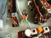
Output from Limiter and Discriminator board goes to the little block pictured and from there to the MPX board. The "little block" appears to be just a terminal block with a brown capacitor across the terminals, input from L & D board connected to one side, output to MPX board connected to the other. The brown capacitor is labeled 241K SOSHIN. I disconnected the wire to the MPX board and could hear the radio at normal levels with my probe on either side of the block. If I touch the wire from the MPX input to the terminal I lose FM. The MPX board is severely dragging down the levels. Anybody have any ideas?
Thinking about moving this thread over to Tuners or Solid State.
With 6060 set to FM, source, I can barely hear radio at full volume.
Output from Limiter and Discriminator board goes to the little block pictured and from there to the MPX board. The "little block" appears to be just a terminal block with a brown capacitor across the terminals, input from L & D board connected to one side, output to MPX board connected to the other. The brown capacitor is labeled 241K SOSHIN. I disconnected the wire to the MPX board and could hear the radio at normal levels with my probe on either side of the block. If I touch the wire from the MPX input to the terminal I lose FM. The MPX board is severely dragging down the levels. Anybody have any ideas?
Thinking about moving this thread over to Tuners or Solid State.
Attachments
Last edited:

Ylli
Super Member
That 'block' with the 241k capacitor across it looks like an inline trap. I don't see it on the schematic nor do I see it on the pictures in the service manual. Could be a factory mod. So with the wire disconnected from the left hand pin of that 'block' (it's an adjustable inductor), you get reasonable signal on either pin of the inductor, but when you connect the wire back up the audio goes **way** down?
With power on, check for any DC voltage on either pin of the inductor. With power off, check the resistance from either inductor pin to ground. Does you MPX board have the 8.2K resistor as shown in post #218, 219, 220 here: https://audiokarma.org/forums/index.php?threads/sony-6060f.897531/page-11#post-13423545 ?
With power on, check for any DC voltage on either pin of the inductor. With power off, check the resistance from either inductor pin to ground. Does you MPX board have the 8.2K resistor as shown in post #218, 219, 220 here: https://audiokarma.org/forums/index.php?threads/sony-6060f.897531/page-11#post-13423545 ?
So with the wire disconnected from the left hand pin of that 'block' (it's an adjustable inductor), you get reasonable signal on either pin of the inductor, but when you connect the wire back up the audio goes **way** down?
Yes.
With power on, check for any DC voltage on either pin of the inductor. With power off, check the resistance from either inductor pin to ground.
Power off - Both pins to ground - Open
Power on - 1.6V on both pins
Yes it has the 8.2K resistor, all 4 are identical to your picture.
When you stated adjustable inductor the light came on (about the "block" anyway), there is a plastic barrel with threads and a slotted screw head inside the metal housing like it is meant to be adjusted if necessary and some very fine wires going to both pins . I have a parts unit with a lower serial number that does not have this inductor.
Ylli
Super Member
Not sure what they are trying to 'trap out' at that point. I pulled what I could find for service supplements, and there was no mention of adding this. ..or the 8.2K resistor. The MPX board needs everything including the 19KHz pilot. So let's just leave that alone.When you stated adjustable inductor the light came on (about the "block" anyway), there is a plastic barrel with threads and a slotted screw head inside the metal housing like it is meant to be adjusted if necessary and some very fine wires going to both pins . I have a parts unit with a lower serial number that does not have this inductor.
I would have expected 8.2K. Perhaps we are not looking at what I thought we were looking at.Power off - Both pins to ground - Open
I would have expected zero. Can you trace it back and confirm that the shielded cable with the orange insulation attaches to the IF/Det board at C232 and that the shielded cable with the green insulation connects to the MPX board at C401 and that 8.2K resistor?Power on - 1.6V on both pins
Is the tuning meter fairly active as you tune across a station?
Last edited:
I would have expected 8.2K. Perhaps we are not looking at what I thought we were looking at.
Bingo!!!
I replaced the cable from the adjustable inductor to the MPX with a longer one so I could stand the board up higher to make it easier to work on. I am reading open on the inductor to ground because I have that cable disconnected at the inductor. I put my meter on the end of the cable toward the MPX and read 0.3 Ohms to ground. Oops! I reversed the leads when I soldered it to the MPX board. I have the shield (ground) connected to C401 and the red lead soldered to the resistor. That explains why I got nothing when it was all put together. I checked that thing a couple times and didn't notice my mistake.
I will get that straightened out tomorrow and then see what I have, probably the static and no stereo that I started with.
Last edited:
Similar threads


- Replies
- 6
- Views
- 444


