
• The move to the new server is done. There are some software and database maintenance updates in process. This has us passing the hat around to help out. We appreciate any donations. Seriously, even a dollar helps. The payment page may be found here - https://www.audiokarma.org/support.html

?Testing Transistors?

Audio signal trace - do you have audio on the inductor?
If yes, then check for audio at that 8.2K resistor.
Annotation 2020-03-27 220407.png
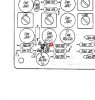
If OK, then check for audio at the top of R404 (emitter of Q401).
Annotation 2020-03-27 215416.png
If OK, then check for audio at the top of R415.
Annotation 2020-03-27 215837.png

Audio level should be very close to the same on all these points. May be a little less on the last point.
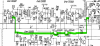
 
So there appears to be a problem in this signal path.
Annotation 2020-03-28 112249.png
Before I have you pull any parts, let's make a couple of ohmmeter measurements. With power off, measure the resistance on both sides of R415. One side should measure near zero, and the other should read a bit less than 1000 ohms (1K). Confirm that you looked for audio on the side that measured near 1K. (confirm that I did not screw up and tell you the wrong side :)). Now measure both sides of R451. One side should measure the same as the top of R451 (bit less than 1K) and the other side should measure 510 ohms higher. Don't think you can get at any other points from the top of the board.

If the above resistance measurements are OK, you will need to pull and test (or just replace) C405, the 100uF coupling capacitor. While it is out, check the DC resistance between ground and the pad where the capacitor negative lead was connected. Should be a bit less than 1.5K. Checking the continuity of the filter coils (L403, L404) here.
 
R415 - 750, 0.2 Audio was on 750ohm side
R451 - 752, 1250

A 100uF 16V cap should be OK, right? That's all I have unless I scavenge an old one somewhere.
 
Well then there is a open in one of the filter coils or there is a cracked solder connection in that line. Resistance from the end of R451 connected to L404, you measured 1250 ohms. Measure the resistance on the pin of L404 that connects to this resistor. Measure the resistance of the other two pins. Move to L403 and measure the resistance on those pins. Looking for the open. If/when you find it, try reflowing the solder on suspected junction.
 
L403 is open. Re-soldered L403 connections. No help. I just happen to have another L403 that reads about 6.5 ohms though.
 
Sold a parts MPX board to a guy from Michigan on the condition he send his bad one back. I should have kept it, his FM is working fine with my parts board.

Results are distorted, somewhat louder FM mono. Levels very low on FM stereo. Good at inductor.

Signal trace same points?
 
If you use the signal tracing technique, is the FM audio clean at the top of R415? Is the stereo light behaving itself?
 
Stereo lamp behaving? Does it come on reliably on an FM stereo station, and go off when turned off station? Trying to determine if if the 19 KHz/38 KHz chain is working properly.
 
Yes, you can check the signal level/quality at C415 & C416. That would be decoded stereo at that point.
Stereo light is always on even when you are tuned to a dead frequency? Look at the voltage on the base of Q410. Should be > 2 volts when tuned to a stereo station and <0.5 volts when not tuned.
 
Back
Top Bottom