
• The move to the new server is done. There are some software and database maintenance updates in process. This has us passing the hat around to help out. We appreciate any donations. Seriously, even a dollar helps. The payment page may be found here - https://www.audiokarma.org/support.html

?Testing Transistors?

Clear FM at C415. Nothing at C416.
Weird. Audio is being injected at the center tap of L406, and the circuitry to C415 is the same as the circuitry to C416.

0V at the base of Q410, stereo lamp always on.
Let's look at this first. With zero volts on the base of Q410, there should be zero on the emitter of Q410. That puts zero volts on the base of Q411 turning it off. The lamp should be off.

Let's measure the voltages on these two transistors:
Q410 B:
Q410 C:
Q410 E:

Q411 B:
Q411 C:
Q411 E:
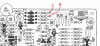
 
Readings on Q410 and Q411

Q410: B=0V, C=9.26V, E=0V Mono........same in Stereo
Q411: B=0V, C=8.7V, E=0V Mono.............same in Stereo

Going to Stereo mode does nothing. Stereo light always on. FWIW muting works. I only have left channel on FM.
 
Last edited:
The 11 volt buss is low (Q10-C should be +11), and there doesn't seem to be any rectified signal from the frequency double (Cathodes of D410, D402). Something in the MPX chain may be drawing too much current.

Let's start by measuring the voltage on both sides of R413 (300 ohm). One side should be +15 from the power supply and the other should be +11.
Then I think we are going to need to measure the voltage on the base, collector and emitter of Q401, Q402, and Q403. Do this when tuned to a dead spot.
 
R413: 14.3V 9.27V

Q401: C=9.0V, B=4.1V, E=3.5V
Q402: C=9.14V, B=1.7V, E=1.12
Q403: c=9.25V, B=2.15V, E=5.83V
 
Nothing jumps out as bad. Voltages are generally low due to the low 11 volt buss. Is the FM Auto/Mono switch set to FM Auto?
These were with the unit tuned to a dead spot on the dial? The noise gate (Q408/Q409) has a high output (as seen at Q402 base) which indicate low hiss, i.e. tuned to a station.

Is an oscilloscope available?

Let's remove Q411. This should cause the stereo light to go out and put the unit in mono mode. Do you get audio from both channels?

Add a jumper across (short) C434. This should put the unit in stereo mode. Stereo light should come on full brightness. Tune to a stereo station, audio still only on one channel?
 
Jumper across C434. Stereo light same. Radio left channel, static right channel.

Don't have a scope but I can get my hands on one. Old employer (phone company) has scopes they never, ever use. I could borrow one from ex-coworker, he'd probably say just keep it. I had to use one once in the 10 years I was in the CO and I don't remember anyone else ever using one.
 
Is the stereo light brighter when C434 is shorted? Is the stereo lamp the original incandescent or did someone put an LED in there? An LED takes a lot less current and may be getting enough through sneak paths to make it light up.

I'm seeing three issues, and nothing seems to be common, except perhaps that slightly low voltage, and I don't see that as making a significant difference.
1. Stereo light illuminates even after the switch that turns it on has been physically removed.
2. No 19 KHz seems to be getting though to the frequency multiplier - the output of this multiplier should be about 3 volts, but seems to be zero.
3. Right channel MPX audio amps seem inop.

Since at this point we seem to be getting nowhere on 1&2, let's look at 3. You found no audio at C416. Remove both C415 and C416, and use the audio signal trace to look for audio at the indicated points:
Annotation 2020-03-29 165301.png

Then do see if you can get the scope, so we can trace the 19KHz/38KHz through the chain of Q401-Q403.
 
Last edited:
Yes, I replaced all lamps except tuning meter with LEDs, recapped unit around 2013, FM Stereo went out about 2 years ago. I thought about mentioning the fact that the stereo lamp was an LED, sorry I didn't.

Clean, clear audio at R517 and R519, Mode switch Mono or FM Stereo Auto, no difference.

Time to quit for the day, time to make dinner. OK?
Tomorrow through Friday I won't be here until later afternoon (around 4pm). I have to get next years firewood under cover so it finishes drying. OK?

I'll call about the scope tomorrow.
 
Whenever you can. I may post some additional thoughts in the meantime.
Clean, clear audio at R517 and R519, Mode switch Mono or FM Stereo Auto, no difference.
Progress.

Stereo lamp: Not having a lot of luck finding definitive specs on PL806, the Stereo indicator lamp. I did find one place that said 8 volt/30mA, but no confirmation. Looking at the way it is connected in circuit, (connected to +15 volt supply, with a series 270 ohm resistor and 1K across the lamp) 8V/30mA makes sense. Do you know what rating LED was installed? Just a plain diode or one with a built in series resistor? We may need to tweak that shunt resistor to get enough current through it when the lamp is not energized.

Right channel audio path: Since they are out of circuit, check C415 and C416. If you don't have a capacitor checker, just use your ohmmeter to check for leakage. When you connect the ohmmeter, the resistance should start out relatively low, but drift up to out of range high - but I suspect you knew this. Then we can check the DC operating voltages on Q405 and Q407. Per the schematic, these should be:

Q405-E: 0.67V
Q405-B: 1.2V
Q405-C: 2.9V

Q407-E: 2.35V
Q407-B: 2.9V
Q407-C: 12.2V

If those are OK, you can check the audio from the input of these amplifiers to the speaker outputs by injecting some 'body hum'. Power up the unit and set the volume control at what would be normal listening levels. Physically touch the base of Q404 with your finger (or touch it with a metal screw driver that you are touching the shaft of, careful not to short anything). You should hear a hum out of the left channel. Now do the same on the base of Q405. You should hear a hum of the same volume out of the right channel.
 
Progress.

I thought we made more progress yesterday than today but since you know what you are doing and I don't I will defer to your judgement.

Stereo lamp: Not having a lot of luck finding definitive specs on PL806, the Stereo indicator lamp. I did find one place that said 8 volt/30mA, but no confirmation. Looking at the way it is connected in circuit, (connected to +15 volt supply, with a series 270 ohm resistor and 1K across the lamp) 8V/30mA makes sense. Do you know what rating LED was installed? Just a plain diode or one with a built in series resistor? We may need to tweak that shunt resistor to get enough current through it when the lamp is not energized.

Plain diode LED. I have a 5.5K series resistor installed with it. I remember being surprised that I had to go so high to get the brightness down enough to look original, everything I read had recommended much lower values. I used 1K series resistors on the LEDs for the FM and AM indicator. Brightness looked original on all and the Stereo LED was on with stereo and OFF with Mono.

R807 is sitting on the PS board. It is big, it looks like it could be 1 Watt but the parts list says RC 1/2 so it must be 1/2 W, right? It only has 3 bands, Black-Red-Gold.

When you connect the ohmmeter, the resistance should start out relatively low, but drift up to out of range high - but I suspect you knew this.

No, I didn't know that. The only way I know to check a cap is with an analog meter. Set it to 10Kohm scale, reverse polarity and if the cap is large enough the meter will kick a little showing capacitance. At the telco we used capacitance kick to gauge the distance to an open in a cable pair.

I'll be back tomorrow with the rest of those test results.
 
R807 is sitting on the PS board. It is big, it looks like it could be 1 Watt but the parts list says RC 1/2 so it must be 1/2 W, right? It only has 3 bands, Black-Red-Gold.
Gotta be a brown band at the start. 1K = Brown-black-red. Gold is 5%. And worst case power dissipation (occurs if the bulb is burned out) would be about 0.14 W

No, I didn't know that. The only way I know to check a cap is with an analog meter. Set it to 10Kohm scale, reverse polarity and if the cap is large enough the meter will kick a little showing capacitance. At the telco we used capacitance kick to gauge the distance to an open in a cable pair.
Works the same with a digital meter. If the capacitor is fully discharged to start, the meter will initially read zero ohms, and then increase until it goes off scale hihg. Swap the leads and the meter will read a -negative- resistance, increase through zero and one again go to off scale high. The speed at which the indicated resistance increases is an indication of the value of the cap. Charges fast = small value cap, charges slow = large value cap. If it does increase to 1 meg or more, it is electrically leaky.
 
just a thought about the low voltages, are the drop resistors still on value? If R413 is high, you'll get excessive drop. Same on whatever supplies that. Probably going to have to lift one end from the board to get an accurate measure on that though. The caps and rest of the circuitry will mess up the reading.
 
just a thought about the low voltages, are the drop resistors still on value? If R413 is high, you'll get excessive drop. Same on whatever supplies that. Probably going to have to lift one end from the board to get an accurate measure on that though. The caps and rest of the circuitry will mess up the reading.
Certainly wouldn't hurt to check the resistance of R413. The 15 volt supply itself is also a bit low - interesting as the power supply appear to use 2x 7.5 volt Zeners in the regulator for a 15 volt reference, and with the pass transistors 0.7 volt B_E drop, that leaves 14.3 volts for the 5 volt bus.
 
I suppose if it was really a problem one of those 7.5v zeners could be swapped for an 8.1v unit, but if it worked new with those value parts, it should still work. I'm generally not real keen on messing with original component values unless there is a really good reason for it.
 
Both caps good, went off scale.

Transistors good.

Q405: E=0.67V, B=1.26V, C=3.24V
Q407: E=2.64V, B=3.23V, C=12.5V

Put ground on base of Q404 and Q405, hum on left channel only.

R413=295ohms
 
Put ground on base of Q404 and Q405, hum on left channel only.
The environment is full of 60 Hz EMF from the electrical distribution system and your body acts as an antenna and picks some of it up. By touching the base, you aren't grounding it, you are injecting that hum voltage into the amplifier, and that allows you to determine if the path from the point you touch to the output is functional.

Transistor voltage are good (as you surmised). Let's try injecting the hum at the outputs of the MPX board. This is where the shielded cables leave the board at R484 and R465 (1K) [I think these are the right designators, the schematic is a bit hard to read]
Annotation 2020-03-30 170454.png
If you switch to AM, do you get output from both channels?
 
Back
Top Bottom