Hi All,
I've just finished to restore another beast: The Allen Organ C-3, AKA Allen Organ 60.
I found one, and then it took me some time to get a second one to be able to make an identical pair.
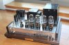
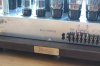
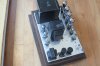
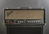
Here is how they look like:

Very little info on that beastly beast. Date: unknown. Designer:unknown. Nothing.
All transformers are made by the AirDesign company from PA. Almost no info on the AirDesign company.
Thanks to hammr7 member to give me some info on it:
"Airdesign was formed by Leon Edward Pamphilon during WWII to supply high quality transformers for military applications. The company continued after the war by supplying consumer applications.
I know they tried to branch out (I have seen other airdesign electrical components) but I don't remember
seeing much from them after the early 1960's, and don't know whether they shut down, were bought out,
or morphed into something else. They were located at 241 Fairfield Ave., Upper Darby, Pa, which by the
early 1980's (and possibly a decade earlier) was home to the Bible and Medical Missionary Fellowship
(later known as Interserve). I think Pamphilon died in the late 1970's or early 1980's."
Maybe some other AKer have more info. Please let us know
Unlike the 90 model this is not a Webster design. AirDesign with Allen Organ's input? Who knows.
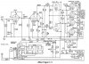
Here is the schematic I found and cleaned up:
When I got the first one was working. The second one wasn't.
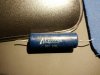
Both had leaky coupling caps upsetting the bias level and making the power tube red plate.
Watch for those
Just as an assessment exercise, I changed the coupling caps, add an RCA input and let's give it a listen.
Well the amps produced a beautiful sound, with a deep audio signature, candidate for a restoration by my standards.
They were noisy: hum, buzz, and "sea waves" noise were present. Kinda normal for a 50+ year old piece, therefore I wasn't concern with this.
I asked Dave G. for his opinion on that beast. Dave immediately spotted a problem on the 6L6 driver tube which was way too cold biased, cautioned me to not go SS rectification due to the 1Kv supply, which I reluctantly agreed as I don't particularly like tube rectifier. I have a bad karma with those: I look at them and they immediately arc ...
...
So I decided to tackle the restoration by phase.
1) The PS: I modeled the PS with Duncan PS II and I used a 50uF after the choke,
then a 30R 5W resistor, then 200uF with a 4.7uF film cap. This is my B+.
From there I fed the voltage regulator, the CT OT primary and the B+x supply rail.

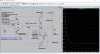
2) New Bias circuit: I used a simple circuit I modeled with Lt Spice and it happened to be exactly what I've got in real life. I use a 100 VAC supply, once bridged rectified gets me a 133 VDC.
That feds my bias and balance circuit similar with the AO75 I know well.
Please note that a loss of pot wiper results is more bias applied to the driver tube, so it is a safer design.
3) Quiet power stage: One odd thing I stumble upon was the wiring of the 6L6s. One side of the heater was connected to ground as the heater winding did not have a CT. Ok I get it.
But, they used that heater side as a bus to ground throughout the amp.
For example all 6l6 cathodes were connected to that heater side as a path to ground. I never saw that before.
I removed all that, installed a virtual ground heater, and wired the 6L6 cathodes to ground via
sensing 10R resistor and by side, so 2 cathodes tied together to a 10R resistor to ground. That way I am able to measure the current going through 2 6L6s, per side. This is not perfect but good enough for biasing and balancing the 4 6L6.
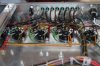
I also installed a pure silver #14 wire ground bus where all the paths to ground go as a star ground scheme.
At the end of all that, the power stage of the amp was much very quiet. No hum, noise gone.
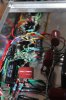
Before the fixed bias was running the 6L6 at 42mA per tube, @ 432V so at 80% maximum plate dissipation.
I could bias the 2 x 6L6 from 30ma to 90ma, so perfect to test all 6L6 family and Co.
4) Working my way up: I've done nothing on the splitter. And for the 6AU6 I just converted it to a triode to get less hiss and less gain. It worked nicely. I used a cathode bypass film cap of 8.2uF, which was enough.
I changed the pentode socket to install one with a shield.
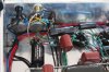
Other things I have done:
1) While I was there I added a fuse in the high voltage supply CT as indicated in the schematic but not implemented in the actual amp.
2) I added a CL60 5 A / 10 R inrush thermistor in the primary supply.
3) Because I need a new PT for the bias supply, I asked Heyboer to make me custom PT to:
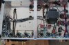
5) I added a barrier strip to manage the line voltage safely and be able to adjust the bucking level if needed.
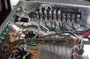
I reached the AK posting limit: to be continued...
I've just finished to restore another beast: The Allen Organ C-3, AKA Allen Organ 60.
I found one, and then it took me some time to get a second one to be able to make an identical pair.
Here is how they look like:
Very little info on that beastly beast. Date: unknown. Designer:unknown. Nothing.
All transformers are made by the AirDesign company from PA. Almost no info on the AirDesign company.
Thanks to hammr7 member to give me some info on it:
"Airdesign was formed by Leon Edward Pamphilon during WWII to supply high quality transformers for military applications. The company continued after the war by supplying consumer applications.
I know they tried to branch out (I have seen other airdesign electrical components) but I don't remember
seeing much from them after the early 1960's, and don't know whether they shut down, were bought out,
or morphed into something else. They were located at 241 Fairfield Ave., Upper Darby, Pa, which by the
early 1980's (and possibly a decade earlier) was home to the Bible and Medical Missionary Fellowship
(later known as Interserve). I think Pamphilon died in the late 1970's or early 1980's."
Maybe some other AKer have more info. Please let us know
Unlike the 90 model this is not a Webster design. AirDesign with Allen Organ's input? Who knows.
Here is the schematic I found and cleaned up:
- It is a fixed bias design. I like it, especially for high power amp. And the bias has its dedicated PT !
- It is a 2 6L6 per side, for 4 in total, but each tubes has its own winding. No parallel tubes per say. That's interesting.
- It has a driver tube in front of the power tubes, like the 75 and 90 model.
- The second AF stage it direct coupled with the splitter, within the first 6SN7.
- The screen voltage is the B+ voltage minus 150V with OC3 tube voltage regulator. That's pretty cool.
- The OT has it's own feedback winding. That's even cooler to me, although feedback adjustment is not possible.
- The input tune is a 6AU6, an excellent AF pentode.
- It has a choke input PS with 1000V CT massive PT. Ouch.
When I got the first one was working. The second one wasn't.
Both had leaky coupling caps upsetting the bias level and making the power tube red plate.
Watch for those
Just as an assessment exercise, I changed the coupling caps, add an RCA input and let's give it a listen.
Well the amps produced a beautiful sound, with a deep audio signature, candidate for a restoration by my standards.
They were noisy: hum, buzz, and "sea waves" noise were present. Kinda normal for a 50+ year old piece, therefore I wasn't concern with this.
I asked Dave G. for his opinion on that beast. Dave immediately spotted a problem on the 6L6 driver tube which was way too cold biased, cautioned me to not go SS rectification due to the 1Kv supply, which I reluctantly agreed as I don't particularly like tube rectifier. I have a bad karma with those: I look at them and they immediately arc
...So I decided to tackle the restoration by phase.
- PS upgrade.
- Addition of a bias and balance pot for the new bias circuitry and supply.
- Getting the 6L6 stage working quietly first.
- Then working my way from the splitter to the first pentode.
1) The PS: I modeled the PS with Duncan PS II and I used a 50uF after the choke,
then a 30R 5W resistor, then 200uF with a 4.7uF film cap. This is my B+.
From there I fed the voltage regulator, the CT OT primary and the B+x supply rail.
2) New Bias circuit: I used a simple circuit I modeled with Lt Spice and it happened to be exactly what I've got in real life. I use a 100 VAC supply, once bridged rectified gets me a 133 VDC.
That feds my bias and balance circuit similar with the AO75 I know well.
Please note that a loss of pot wiper results is more bias applied to the driver tube, so it is a safer design.
3) Quiet power stage: One odd thing I stumble upon was the wiring of the 6L6s. One side of the heater was connected to ground as the heater winding did not have a CT. Ok I get it.
But, they used that heater side as a bus to ground throughout the amp.
For example all 6l6 cathodes were connected to that heater side as a path to ground. I never saw that before.
I removed all that, installed a virtual ground heater, and wired the 6L6 cathodes to ground via
sensing 10R resistor and by side, so 2 cathodes tied together to a 10R resistor to ground. That way I am able to measure the current going through 2 6L6s, per side. This is not perfect but good enough for biasing and balancing the 4 6L6.
I also installed a pure silver #14 wire ground bus where all the paths to ground go as a star ground scheme.
At the end of all that, the power stage of the amp was much very quiet. No hum, noise gone.
Before the fixed bias was running the 6L6 at 42mA per tube, @ 432V so at 80% maximum plate dissipation.
I could bias the 2 x 6L6 from 30ma to 90ma, so perfect to test all 6L6 family and Co.
4) Working my way up: I've done nothing on the splitter. And for the 6AU6 I just converted it to a triode to get less hiss and less gain. It worked nicely. I used a cathode bypass film cap of 8.2uF, which was enough.
I changed the pentode socket to install one with a shield.
Other things I have done:
1) While I was there I added a fuse in the high voltage supply CT as indicated in the schematic but not implemented in the actual amp.
2) I added a CL60 5 A / 10 R inrush thermistor in the primary supply.
3) Because I need a new PT for the bias supply, I asked Heyboer to make me custom PT to:
- use it as bucking transformer to go from 120+VAC to 117 VAC via a 6.3 VAC CT 4 A winding.
- add an extra 6.3 VAC to power the 2 6SN7 / 6AU6 heaters, to save the old PT heater current with a second 6.3 VAC CT 4 A winding. The old PT now only power the 6L6 heaters. The new 6.3 VAC has a CT.
- generate 100 VAC 200 mA for the bias supply (I know 200 mA is overkill but they could make it so why not).
- fit under chassis.
5) I added a barrier strip to manage the line voltage safely and be able to adjust the bucking level if needed.
I reached the AK posting limit: to be continued...