• The move to the new server is done. There are some software and database maintenance updates in process. This has us passing the hat around to help out. We appreciate any donations. Seriously, even a dollar helps. The payment page may be found here - https://www.audiokarma.org/support.html

The Fisher X100 - Right Channel Out


Thanks Larry. Side by side, the photofacts looks the same as the Fisher Service manual, but part numbers are different.

I have a question about parts:
For capacitors, which do you recommend? Orange drops? Metalized tubular axials?

For resistors, in the Fisher Service manual, some are 1/3W. Is it ok to use 1/2W?

And off topic to my fisher.... I have a Marantz 2220b. Is it bad for the unit to run 4ohms? It's 8 ohm output.

Thank again.
 
Thanks Larry. Side by side, the photofacts looks the same as the Fisher Service manual, but part numbers are different.

I have a question about parts:
For capacitors, which do you recommend? Orange drops? Metalized tubular axials?

For resistors, in the Fisher Service manual, some are 1/3W. Is it ok to use 1/2W?

And off topic to my fisher.... I have a Marantz 2220b. Is it bad for the unit to run 4ohms? It's 8 ohm output.

Thank again.

While we're waiting on Larry to respond I'll give my 2c for what it's worth.

- For coupling caps I typically use yellow film caps. Often it is Illinois caps, but I'm not afraid to buy no name stuff on the big auction site. Orange drops are fine too. There are some that go for russian oil caps or boutique caps. I'm not in that camp. Just make sure the voltage handling is same or higher than original.

- 1/2W is just fine. It's ok to go up in power handling, but never down.

- Hard to say about if its' ok to go with 4ohm on the Marantz 2220B. (I have one btw.) It might make a difference if you run it hard or just at normal levels. I'd say that if you try that, I'd recommend that it be serviced and in good working condition first. Others with more specific knowledge of the Marantz might chime in. (I am not afraid of using my Polk 7B's which are about 6 ohm-ish.)
 
Last edited:
While we're waiting on Larry to respond I'll give my 2c for what it worth.

- For coupling caps I typically use yellow film caps. Often it is Illinois caps, but I'm not afraid to buy no name stuff on the big auction site. Orange drops are fine too. There are some that go for russian oil caps or boutique caps. I'm not in that camp. Just make sure the voltage handling is same or higher than original.

- 1/2W is just fine. It's ok to go up in power handling, but never down.

- Hard to say about if its' ok to go with 4ohm on the Marantz 2220B. (I have one btw.) It might make a difference if you run it hard or just at normal levels. I'd say that if you try that, I'd recommend that it be serviced and in good working condition first. Others with more specific knowledge of the Marantz might chime in. (I am not afraid of using my Polk 7B's which are about 6 ohm-ish.)

Thanks Tim. Good news! I found the problem: a bad capacitor on V7. the .047 connected to V1. I tested for continuity and it was open/bad. I spliced in a temp (still waiting on parts to recap the entire unit). I can't tell you how good it feels to have found it. It was driving me nuts. I'll report back after I recap it.

RE: 4ohm on the Marantz I picked up a set of Boston Acoustics Sub Stat6. It has a non-powered sub woofer. So I twisted leads positive to positive and neg to neg. Because each piece is 8 ohms, I think that makes them 4ohm....correct? They sound pretty good, I like them for my office. I cleaned and lubed parts in the unit but haven't serviced it. Thats another day. Circuit boards are more daunting to me than point to point.
 
Photofacts are ok, but I tend to trust the FISHER Manuals more (less mistakes, although there can be some) and they are drawn by the engineers that designed them. Sometimes you don't have a choice, and photofact is go-to.


I'm with Tim. Yellow Axials, or if space is super tight, I use Cornell dublier DME series radials. O.D.'s can get quite large physically. Or if you like, WIMA mkp on tape mounting has long leads, and are quite good. I can't tell the difference sound wise between the 3 so I usually look at physical size needed, and get the cheapest. (My middle name is Jack Benny! LOL)

1/2w resistors are fine in place of 1/3w.

No rating on the 2220B for 4ohms, although the manuals say 4 to 16oHm. With 20W into 8ohm @ 20Hz to 20kHz both channels driven (RMS rating for 1974 FTC ruling), I'd be loath to use it @ 4ohms the way you are. Separate your leads and connect them to the "A" & "B" speakers, then select A-B. To see if your Marantz parallels or series the speaker connections, put a pair on the "A" or MAIN speakers and select A-B on the front. If it plays they are paralleled (4ohms aggregate), if no sound come out they'll be in series (16ohm aggregate). 16ohm is way less of a load on the amp, and you may find it is a negligible drop in S.L., if any.

The other way to series the speakers is to connect POSITIVE of speaker 1 to Positive terminal on 2220B, Then the NEG lead to the Pos lead of spkr 2, then the NEG of spkr 2 goes to NEGATIVE TERMINAL on 2220B.

 
Photofacts are ok, but I tend to trust the FISHER Manuals more (less mistakes, although there can be some) and they are drawn by the engineers that designed them. Sometimes you don't have a choice, and photofact is go-to.


I'm with Tim. Yellow Axials, or if space is super tight, I use Cornell dublier DME series radials. O.D.'s can get quite large physically. Or if you like, WIMA mkp on tape mounting has long leads, and are quite good. I can't tell the difference sound wise between the 3 so I usually look at physical size needed, and get the cheapest. (My middle name is Jack Benny! LOL)

1/2w resistors are fine in place of 1/3w.

No rating on the 2220B for 4ohms, although the manuals say 4 to 16oHm. With 20W into 8ohm @ 20Hz to 20kHz both channels driven (RMS rating for 1974 FTC ruling), I'd be loath to use it @ 4ohms the way you are. Separate your leads and connect them to the "A" & "B" speakers, then select A-B. To see if your Marantz parallels or series the speaker connections, put a pair on the "A" or MAIN speakers and select A-B on the front. If it plays they are paralleled (4ohms aggregate), if no sound come out they'll be in series (16ohm aggregate). 16ohm is way less of a load on the amp, and you may find it is a negligible drop in S.L., if any.

The other way to series the speakers is to connect POSITIVE of speaker 1 to Positive terminal on 2220B, Then the NEG lead to the Pos lead of spkr 2, then the NEG of spkr 2 goes to NEGATIVE TERMINAL on 2220B.

Good to know. Thanks!

A question on resistors. The service manual lists different materials - both carbon and composition - and tolerances - +/- 5% and +/- 10%. Do the material or the tolerance matter? The new resistors I'm looking at are premium carbon 5%, Carbon 10% and Metal Film 1%. The metal film are a third the price from the premium. What's the general rule for resistor tolerance? Thanks again!
 
I use metal film resistors most of the time as they are ubiquitous now. Some will swear that carbon comp sound better. Others say carbon comp introduce noise. I have had very good results with metal film so I am in that camp. I will typically shoot for 10% unless the manual spec's better than that.

For cathode measurement resistors (a frequently recommended mod) I use 10 ohm 1/8W (flame proof) metal film at 1% tolerance. This is one of the few where I shoot for very tight tolerance because you want accuracy when you are measuring your tube current. I use 1/8W because I want them to blow before the tube or the output trannie gets cooked. Flame proof metal film will blow with a loud snap! I know, I bridged the cathode with something higher voltage and it blew the little resistor. It did its' job.

Now having said all that. I often go up in power handling in an attempt to get the physical size of the resistor back to the vintage size. Today's 1/4 or 1/2 or 1/3W resistors are really dinky these days. It's hard to dig through the resistor data to determine what is the physical size of the resistors. Not sure my thing will be your thing, but I'll leave you with that.
 
You might want to consider asking to move this thread to the Fisher area. You would get more targetted answers over there.
 
Concur on Metal 1%. 1/4W will do fine on Cathode resistors. My Sansui 1000A would blow the same one about every 6 months just to keep me on my toes. Then I replaced the sockets and no more problems. Never had one go on any of my Fisher's. If you feel more inclined to use a 1/8w that's fine.
 
Hello again.

I recapped the unit and it sounds great to my ear. Huge difference. But some voltages are higher, some lower than the schematic. Should I be concerned? Will it burn out the tubes faster? All advice is appreciated.

I'm just learning how to read schematics, so maybe I've read some of these voltages wrong, but here are voltages as of this morning:

V1 (12ax7)
p6. schematic: 96v / my reading: 76v

V2 (12ax7)
p1 schematic: 150v / my reading: 175v
p6. schematic: 150v / my reading: 168v

V3 (7247)
p1 schematic: 167v / my reading: 180v
p3 schematic: 44v / my reading: 99v (is this too high?)

V4 (EL84)
p3 schematic: 44v / my reading: 44v
p7 schematic: 380v / my reading: 405v when turned on....399v after warming up
p9 schematic: 320v / my reading: 338v

V5 (EL84)
p3 schematic: 44v / my reading: 44v
p7 schematic: 380v / my reading: 405v when turned on....399v after warming up
p9 schematic: 326v / my reading: 347v

V6 (12ax7)
p1 schematic: 99v / my reading: 80v
p6. schematic: 96v / my reading: 83v

V7 (7247)
p1 no voltages listed / my reading: 149v
p6. no voltages listed / my reading: 147v

V8 (12ax7)
p1 schematic: 167v / my reading: 185v
p6. schematic: 100v / my reading: 94v

V9 (EL84)
p3 schematic: 44v / my reading: 44v
p7 schematic: 380v / my reading: 405v when turned on....399v after warming up

V10 (EL84)
p3 schematic: 44v / my reading: 44v
p7 schematic: 380v / my reading: 405v when turned on....399v after warming up

V11 (GZ34/ 5AR4)
p4 & 6 schematic: 730vac / my reading: 767vac (is this too high?)
p2 & 8 schematic: 5vac / my reading: 5.2
 
Hello again.

apologies. I goofed:
I wrote:
V3 (7247)
p1 schematic: 167v / my reading: 180v
p3 schematic: 44v / my reading: 99v (is this too high?) (THIS IS WRONG - no schematic voltages on V3)

V3 CORRECTION:

p1 schematic: 167v / my reading: 180v
p6 schematic: 100v / my reading: 99v

V8 (7247)
p1 no voltages listed / my reading: 149v (THIS IS WRONG)
p6. no voltages listed / my reading: 147v(THIS IS WRONG)

V8 CORRECTION:
p1 schematic: 167v / my reading: 183v
p6 schematic: 100v / my reading: 93v


I recapped the unit and it sounds great to my ear. Huge difference. But some voltages are higher, some lower than the schematic. Should I be concerned? Will it burn out the tubes faster? All advice is appreciated.

I'm just learning how to read schematics, so maybe I've read some of these voltages wrong, but here are voltages as of this morning:


V1 (12ax7)
p6. schematic: 96v / my reading: 76v

V2 (12ax7)
p1 schematic: 150v / my reading: 175v
p6. schematic: 150v / my reading: 168v

V3 (7247)
p1 schematic: 167v / my reading: 180v
p3 schematic: 44v / my reading: 99v (is this too high?)

V4 (EL84)
p3 schematic: 44v / my reading: 44v
p7 schematic: 380v / my reading: 405v when turned on....399v after warming up
p9 schematic: 320v / my reading: 338v

V5 (EL84)
p3 schematic: 44v / my reading: 44v
p7 schematic: 380v / my reading: 405v when turned on....399v after warming up
p9 schematic: 326v / my reading: 347v

V6 (12ax7)
p1 schematic: 99v / my reading: 80v
p6. schematic: 96v / my reading: 83v

V7 (7247)
p1 no voltages listed / my reading: 149v
p6. no voltages listed / my reading: 147v

V8 (12ax7)
p1 schematic: 167v / my reading: 185v
p6. schematic: 100v / my reading: 94v

V9 (EL84)
p3 schematic: 44v / my reading: 44v
p7 schematic: 380v / my reading: 405v when turned on....399v after warming up

V10 (EL84)
p3 schematic: 44v / my reading: 44v
p7 schematic: 380v / my reading: 405v when turned on....399v after warming up

V11 (GZ34/ 5AR4)
p4 & 6 schematic: 730vac / my reading: 767vac (is this too high?)
p2 & 8 schematic: 5vac / my reading: 5.2
 
fair guess much of this is high incoming line voltage. If you can knock the incoming voltage down until the 6.3 vac heater supply actually reads 6.3vac most of this will fall in line.
 
fair guess much of this is high incoming line voltage. If you can knock the incoming voltage down until the 6.3 vac heater supply actually reads 6.3vac most of this will fall in line.

I’m new to this. How do I knock the incoming voltages down?
 
A bucking transformer is the generally preferred solution but if you have a variac on hand, that will do quite nicely for the experiment.

or sometimes just adding a thermistor between the fuse and the power transformer in the unit will knock it down enough. There are probably posts with specifics on where exactly it fits best in an X100. I've never been in one, so i don't know exactly what you've got to work with inside.
 
this is what I did for my X-100-2 and it was good for lowering 3-4 volts, if I'm remembering correctly:
index.php
 
this is what I did for my X-100-2 and it was good for lowering 3-4 volts, if I'm remembering correctly:
index.php

Yep. That's a CL-80 in-rush limiter. I've found them good for about 1.5VAC on the line in side but that might translate to 3 or 4 volts on the high voltage DC inside the amp.
 
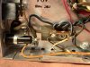
I've attached a photo of my amp power input. Where exactly do I hook a CL-80 or CL-90 on my unit?
Do these parts come in different values/ohms? Would either work? I'm thinking about getting both and starting with the CL-80. Any other advice?
Thanks in advance.
 

Attachments

  • Fisher X-100.JPG
    Fisher X-100.JPG
    149 KB · Views: 8
I've attached a photo of my amp power input. Where exactly do I hook a CL-80 or CL-90 on my unit?
Do these parts come in different values/ohms? Would either work? I'm thinking about getting both and starting with the CL-80. Any other advice?
Thanks in advance.

Either will work. Put electrically in the path with the power switch (which is on the AC side of the power transformer.)
 
Either will work. Put electrically in the path with the power switch (which is on the AC side of the power transformer.)

I could use a hand pointing out where, exactly I might place the CL-80. I've attached a photo. Can you tell me between which 2 points I place it? The unit works so well now, I hate to make a dumb mistake.

Thank you.
 

Attachments

  • Slide1.jpeg
    Slide1.jpeg
    141.9 KB · Views: 11
I'd cut the black wire under "F" and land the two ends of the Black wire on a terminal strip just like the one at "B" and "C" but put the new strip where "F" is located. Then you can attach the CL-80 to the two ends of the black wire on the ends of the new terminal strip. Just giving some ideas.

If you look at the X100 schematic that places the CL-80 between the fuse and the line side of the power transformer.
 
Back
Top Bottom