FlaCharlie
Super Member
I’m always encouraging people to build something themselves that uses tubes. My most recent amp threads feature simple designs that don’t even require the use of solder. And they use a SMPS (switch mode power supply), which also simplifies the DIY process.
Here I’m presenting a similar DIY project for those who are interested in tube preamps.
The popularity of tube preamps has been steadily rising for years now. Perhaps the best proof of this on AK is the massive thread over on the New Gear - Values forum about the little Chinese FX Tube 01 preamp and its various spin-off cousins. That thread has over 5000 posts and half a million views over the past 6+ years.
The use of Class D amplification has also grown tremendously over the same period of time and curiosity about tube preamps has grown in tandem with this trend. Indeed, most of the interest in these preamps seems to be coming from people who use Class D (and SS) amps and want to add some “tube flavor” / “warmth” / “color” to the mix.
The terms can be divisive at times but, bottom line, users of these commercial tube preamps like them because they, subjectively, find that they improve the sound of their Class D / SS based systems.
So this preamp project is aimed specifically at them. Of course, it can be used with a tube amp too.
Many owners of cheap Chinese tube preamps have also done mods to them which indicates an interest in DIY. Tube rolling is popular, of course, as is “upgrading” certain parts, typically caps. But the range of modifications that can be implemented are quite limited and some issues remain.
One issue is that they run their tubes at lower than normal voltages. During a previous preamp breadboarding marathon I tried using the same tube that’s used in the FX at a more “normal” voltage / operating point. I found that it sounded much better than the stock FX op point which was probably chosen for economic reasons.
Unfortunately, the basic operating points of the popular commercial offerings are pretty much set in stone because much of the circuitry, especially the power supply sections, are built with tiny SMD (surface mount) parts which are not DIY friendly. The use of circuit boards also means that modifications to the circuit are difficult. And, in addition, they use tubes whose characteristics are less than optimal when used with Class D (or SS) amps.
I’m a fan of simple, low parts count, bang for the buck circuits. So that’s the philosophy that drives this project. Prospective builders, who have little to no experience with DIY, should have no problem building this. Hopefully this thread will encourage some of them to take the next step and build a tube preamp from scratch.
The basic circuit design I’m presenting here is nothing special. In fact it’s essentially the same as the popular commercial offerings. The difference is that it uses a higher voltage power supply and tubes that are better suited for use with Class D amps. And, because it’s wired point to point, experimentation is much easier.
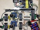
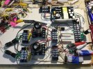
It could be built using the “no solder” methods shown in my amp threads mentioned earlier. Either breadboard style like the Simplissimo or in a chassis, like the RLT 6N6G:
Of course it could also be constructed normally, using soldered connections, or even some combination of the two.
The use of a SMPS, as was done in those two amp build threads, is a major contributor to the goal of simplicity. For this preamp development project (which I’ve been calling Pre4D) I’m using a smaller SMPS that’s a bit more basic than the version I used in those amp projects. Outputs are limited to 300v and 6.3v while the larger version that’s used in the amps also has a 12.6v output and voltage can be adjusted within a limited range.
These are also less expensive. Prices are typically ~$25 shipped from eBay. They’re usually cheaper on AliExpress where I recently found them for ~$19 shipped. Prices vary a lot between sellers so you really need to shop around to get the best price at any given time. And it remains to be seen how the prices will be affected by tariffs.
I experimented with several tube types. They all had two basic characteristics which, IMO, make them well suited for this project.
The first characteristic I screened for is amplification factor (mu). Most all modern amps don’t need any gain from a preamp at all unless the source level is particularly weak. They can produce full power from an input signal that’s lower than a standard line level output. So somewhere along the way the signal must be attenuated (reduced) even if you don’t amplify it further with a preamp. Of course you’ll also need some way to adjust the volume.
One method is to use a so called “passive preamp”, which is just a fancy name for a common volume control. This doesn’t amplify the signal at all. Some prefer this approach while others find it lacking in a variety of ways. A source that has variable output (like a DAC or streamer) can also be used to adjust volume. But, however volume is adjusted, many people also find that the sound is improved when they add a tube preamp, which provides some gain.
The more gain that a tube has the more you need to shunt to ground and this can make fine volume adjustments difficult. For example, one of the common complaints about the FX preamps is that the volume control is too sensitive. A tiny adjustment in the position of the control results in too much of a difference in volume. One reason for this is that the tube they use has a mu (amplification factor) of ~35 and this limits the useful range of the volume control.
As I see it, it’s better to use a tube type that has relatively low mu than one that has a higher mu, unless you actually need more gain. So the tubes I chose to experiment with all have a mu of 10 or less.
The output impedance of a preamp needs to be considerably lower than the input impedance of the amp. From a technical perspective the “ideal” that is often mentioned is a ratio of 1:10. Though this ratio is not a “set in stone rule”, it’s the preferred guideline / goal. This ensures that the preamp can easily drive the amp.
The second characteristic I screened for is the internal plate resistance of the tube.
Though other factors may have some influence on the overall output impedance of a preamp, for a simple circuit like this the output impedance of the tube itself is the dominant factor. This can be calculated easily. It’s simply the plate resistance in parallel with the value of the plate load resistor. The load resistor is a higher value than the plate resistance so, when the parallel value is calculated, the result will be a bit lower than the plate resistance.
This aspect is not generally an issue when you’re using a tube amp because they have higher input impedance, typically 100k. But Class D and SS amps have an input impedance that’s much lower, often 20k and sometimes as low as 10k. So, to cover all our bases with a Class D amp, if we follow the 1:10 guideline that means the ideal output impedance of the preamp should be 1k.
Not many tubes have a plate resistance that low. If a tube with higher plate resistance is used the most common strategy to achieve a low output impedance is to add another tube section which is configured as a cathode follower. But adding a cathode follower makes the circuit more complicated. I prefer to have fewer parts in the signal path.
Fortunately, if you choose the right type of tube there is no need to add a cathode follower. So the tubes I tried all have an internal plate resistance of ~1k or less. This allows the preamp to have just one tube section per channel, which is as simple as it gets.
After auditioning several types that meet these criteria I’ve chosen the 6CW5 / EL86 and its Russian counterpart the 6P43P-E. This is a pentode in a 9 pin miniature bottle. Here it’s wired in triode mode which has a mu of ~8 and its internal plate resistance is right around 1k, perhaps a bit lower at some operating points. After the value of the load resistor is figured in, the output impedance of the tube itself will be under 1k.
Cost and availability were also considered. These tubes are not in current production but there seem to be plenty around and they’re cheap. The two big dealers here in Florida list them for $4 and $7.50. The Russian 6P43P-E can be found on eBay, mostly from Ukrainian sellers. I bought a lot of 10 of them for $31 including shipping.
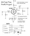
Anyway, I call this preamp the Flow. Here’s the schematic. More details to follow . . .

Here I’m presenting a similar DIY project for those who are interested in tube preamps.
The popularity of tube preamps has been steadily rising for years now. Perhaps the best proof of this on AK is the massive thread over on the New Gear - Values forum about the little Chinese FX Tube 01 preamp and its various spin-off cousins. That thread has over 5000 posts and half a million views over the past 6+ years.
The use of Class D amplification has also grown tremendously over the same period of time and curiosity about tube preamps has grown in tandem with this trend. Indeed, most of the interest in these preamps seems to be coming from people who use Class D (and SS) amps and want to add some “tube flavor” / “warmth” / “color” to the mix.
The terms can be divisive at times but, bottom line, users of these commercial tube preamps like them because they, subjectively, find that they improve the sound of their Class D / SS based systems.
So this preamp project is aimed specifically at them. Of course, it can be used with a tube amp too.
Many owners of cheap Chinese tube preamps have also done mods to them which indicates an interest in DIY. Tube rolling is popular, of course, as is “upgrading” certain parts, typically caps. But the range of modifications that can be implemented are quite limited and some issues remain.
One issue is that they run their tubes at lower than normal voltages. During a previous preamp breadboarding marathon I tried using the same tube that’s used in the FX at a more “normal” voltage / operating point. I found that it sounded much better than the stock FX op point which was probably chosen for economic reasons.
Unfortunately, the basic operating points of the popular commercial offerings are pretty much set in stone because much of the circuitry, especially the power supply sections, are built with tiny SMD (surface mount) parts which are not DIY friendly. The use of circuit boards also means that modifications to the circuit are difficult. And, in addition, they use tubes whose characteristics are less than optimal when used with Class D (or SS) amps.
I’m a fan of simple, low parts count, bang for the buck circuits. So that’s the philosophy that drives this project. Prospective builders, who have little to no experience with DIY, should have no problem building this. Hopefully this thread will encourage some of them to take the next step and build a tube preamp from scratch.
The basic circuit design I’m presenting here is nothing special. In fact it’s essentially the same as the popular commercial offerings. The difference is that it uses a higher voltage power supply and tubes that are better suited for use with Class D amps. And, because it’s wired point to point, experimentation is much easier.
It could be built using the “no solder” methods shown in my amp threads mentioned earlier. Either breadboard style like the Simplissimo or in a chassis, like the RLT 6N6G:
Build This Tube Amp With A Screwdriver
So a few years ago I picked up a Switch Mode Power Supply (SMPS) that's designed for tube circuits. It has separate outputs for 6.3v and 12.6v heaters and a 300v output for the B+. But other projects took precedence so it sat on the shelf for a long time. Some folks over at DIYAudio had...
www.audiokarma.org
My 10 Year Old Granddaughter Builds a Tube Amp
This was actually the first circuit I developed with the convenient SMPS used in the Simplissimo, the breadboard style SE EL34 that I posted previously: https://www.audiokarma.org/forums/index.php?threads/build-this-tube-amp-with-a-screwdriver.1061713/ While the circuit used here is different...
audiokarma.org
Of course it could also be constructed normally, using soldered connections, or even some combination of the two.
The use of a SMPS, as was done in those two amp build threads, is a major contributor to the goal of simplicity. For this preamp development project (which I’ve been calling Pre4D) I’m using a smaller SMPS that’s a bit more basic than the version I used in those amp projects. Outputs are limited to 300v and 6.3v while the larger version that’s used in the amps also has a 12.6v output and voltage can be adjusted within a limited range.
These are also less expensive. Prices are typically ~$25 shipped from eBay. They’re usually cheaper on AliExpress where I recently found them for ~$19 shipped. Prices vary a lot between sellers so you really need to shop around to get the best price at any given time. And it remains to be seen how the prices will be affected by tariffs.
I experimented with several tube types. They all had two basic characteristics which, IMO, make them well suited for this project.
The first characteristic I screened for is amplification factor (mu). Most all modern amps don’t need any gain from a preamp at all unless the source level is particularly weak. They can produce full power from an input signal that’s lower than a standard line level output. So somewhere along the way the signal must be attenuated (reduced) even if you don’t amplify it further with a preamp. Of course you’ll also need some way to adjust the volume.
One method is to use a so called “passive preamp”, which is just a fancy name for a common volume control. This doesn’t amplify the signal at all. Some prefer this approach while others find it lacking in a variety of ways. A source that has variable output (like a DAC or streamer) can also be used to adjust volume. But, however volume is adjusted, many people also find that the sound is improved when they add a tube preamp, which provides some gain.
The more gain that a tube has the more you need to shunt to ground and this can make fine volume adjustments difficult. For example, one of the common complaints about the FX preamps is that the volume control is too sensitive. A tiny adjustment in the position of the control results in too much of a difference in volume. One reason for this is that the tube they use has a mu (amplification factor) of ~35 and this limits the useful range of the volume control.
As I see it, it’s better to use a tube type that has relatively low mu than one that has a higher mu, unless you actually need more gain. So the tubes I chose to experiment with all have a mu of 10 or less.
The output impedance of a preamp needs to be considerably lower than the input impedance of the amp. From a technical perspective the “ideal” that is often mentioned is a ratio of 1:10. Though this ratio is not a “set in stone rule”, it’s the preferred guideline / goal. This ensures that the preamp can easily drive the amp.
The second characteristic I screened for is the internal plate resistance of the tube.
Though other factors may have some influence on the overall output impedance of a preamp, for a simple circuit like this the output impedance of the tube itself is the dominant factor. This can be calculated easily. It’s simply the plate resistance in parallel with the value of the plate load resistor. The load resistor is a higher value than the plate resistance so, when the parallel value is calculated, the result will be a bit lower than the plate resistance.
This aspect is not generally an issue when you’re using a tube amp because they have higher input impedance, typically 100k. But Class D and SS amps have an input impedance that’s much lower, often 20k and sometimes as low as 10k. So, to cover all our bases with a Class D amp, if we follow the 1:10 guideline that means the ideal output impedance of the preamp should be 1k.
Not many tubes have a plate resistance that low. If a tube with higher plate resistance is used the most common strategy to achieve a low output impedance is to add another tube section which is configured as a cathode follower. But adding a cathode follower makes the circuit more complicated. I prefer to have fewer parts in the signal path.
Fortunately, if you choose the right type of tube there is no need to add a cathode follower. So the tubes I tried all have an internal plate resistance of ~1k or less. This allows the preamp to have just one tube section per channel, which is as simple as it gets.
After auditioning several types that meet these criteria I’ve chosen the 6CW5 / EL86 and its Russian counterpart the 6P43P-E. This is a pentode in a 9 pin miniature bottle. Here it’s wired in triode mode which has a mu of ~8 and its internal plate resistance is right around 1k, perhaps a bit lower at some operating points. After the value of the load resistor is figured in, the output impedance of the tube itself will be under 1k.
Cost and availability were also considered. These tubes are not in current production but there seem to be plenty around and they’re cheap. The two big dealers here in Florida list them for $4 and $7.50. The Russian 6P43P-E can be found on eBay, mostly from Ukrainian sellers. I bought a lot of 10 of them for $31 including shipping.
Anyway, I call this preamp the Flow. Here’s the schematic. More details to follow . . .


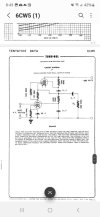


 As for signal tubes, the very low mu of a 12B4 would seem to be just right for a no-feedback preamp.