• The move to the new server is done. There are some software and database maintenance updates in process. This has us passing the hat around to help out. We appreciate any donations. Seriously, even a dollar helps. The payment page may be found here - https://www.audiokarma.org/support.html

The Flow Pre4D - A DIY Tube Preamp

I banged one together using one triode per channel, it was still sufficiently low output impedance. I did the very lazy output impedance check method. Set the voltage to 2v p-p, load it down with a pot until it drops to 1v, measure the pot. Pot value = output impedance. Pretty sure I used a 2k pot and it ended up somewhere right around 1000 ohms.

I was contemplating LED bias just because I've never used that on anything. Free pilot light too.
Yeah, the data sheet says each triode has an Rp of 1.3k. So with the load resistor figured in output impedance should be just over 1k.

As I said, I got a little nervous about them because two of the NOS ones I bought, from two different sellers, had shorts. The second one was purchased to replace the first one. Hopefully just a streak of bad luck.

I didn’t try LEDs on this project but I tried them on the 6SL7 when I had the Simplissimo amp breadboarded. Stephe uses them and likes them so I got some of the ones she recommends.

I immediately noticed an increase in detail. But very shortly, literally within 5 minutes, listening fatigue set in and my ears were hurting so I switched back to battery grid bias. So obviously, YMMV. Maybe you’ll like them. I always encourage experimentation.
 
Last edited:
Take a look and see??

When I started the thread the SMPS could still be found at the prices I mentioned previously on eBay and AliExpress if you shop around. Prices vary, some are always higher. May have changed since then??

For breadboard type sockets search “tube socket experiment prototype” on eBay. I’ve never seen them listed on AliExpress.

The 9 pin (and other) breadboard sockets used to be cheap from Chinese sellers. I recently bought 4 and paid $45 including shipping. Now they’re all charging crazy prices for shipping ($180??) in protest. Who knows how long that will last. Pete Millet also sells them on eBay. I presume he makes them himself in the USA. Looks like a pair from him will run you ~$45 if you use ground shipping. So twice as expensive.
Much cheaper to use normal sockets and solder at the moment. If you’re breadboarding you can mount them using standoffs.
well, the price is fine, and its readily
available, hence my question
about
tariffs on this smps from china
 
Last edited:
well, the price is fine, and its readily
available, hence my question
about
tariffs on this smps from china
Well the tariff situation seems to change daily. I don’t have any more insight into what will happen than anyone else. If you’re asking if I’ve been charged anything extra then, no I haven’t. Yet.

I do know that there has been a longstanding tariff exemption on Chinese goods that cost under $800 called the “de minimus” exemption. A while back I heard that this was set to expire at the end of this month. Whether it will or not depends on the waffler in chief.

Maybe you should order one of these, which ships from Kentucky :rflmao::

 
Last edited:
Well the tariff situation seems to change daily. I don’t have any more insight into what will happen than anyone else. If you’re asking if I’ve been charged anything extra then, no I haven’t. Yet.
i asked the group in the hope that someone had a legitimate answer
I do know that there has been a longstanding tariff exemption on Chinese goods that cost under $800 called the “de minimus” exemption. A while back I heard that this was set to expire at the end of this month.
the end date for may 2 was set april 2. as of 1m ago that deadline is still in play.
Whether it will or not depends on the waffler in chief.

Maybe you should order one of these, which ships from Kentucky :rflmao::

certainly not; maybe you can ask your magic 8ball in stead.
 
i asked the group in the hope that someone had a legitimate answer

the end date for may 2 was set april 2. as of 1m ago that deadline is still in play.

certainly not; maybe you can ask your magic 8ball in stead.
I’m not sure if there are any “legitimate answers” at this point since tariff details seem to fluctuate day to day. Even government officials sometimes make conflicting statements on the same day.

Thanks for the definitive update on the end date of the “deminimus exemption”. Of course, that could change too. But if you’ve got your eye on anything from China it might be a good idea to order now. I’ve picked up a few things in anticipation.
 
I have my eye in a Chinese made CD transport, but now I'm waiting on the updated version that looks better and has a few added features.
Even with the tarrif, the price won't be that bad.
The tarrif's are a moving target who knows where the spinning wheel will stop.
 
I was actually looking for a crystal ball that appears broken, ideally with an "out of service" sign inside it to put on my desk at work.
 
you know, it occurs to me I know someone who works at the local college in their glass arts department. I haven' seen her in a while but maybe next time we cross paths I'll ask if she can make something like that for me.
 
you know, it occurs to me I know someone who works at the local college in their glass arts department. I haven' seen her in a while but maybe next time we cross paths I'll ask if she can make something like that for me.
One with mercury and a heater inside would look cool. :biggrin:
 
That gets into chemical safety bs at work that i have no desire to deal with. Im the admin of that program so it would hypocritical of me to not follow it. Also being extremely familiar with it, i have no desire to do it.
 
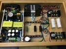
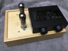
So I decided to move this from breadboard to build. Once again I’m using a small bamboo box. It was sourced from Amazon and its outside dimensions are 6” x 9”. Most of it is built with solder and normal terminal strips. I decided to keep the breadboard type terminal blocks to mount the output caps. This makes it easier to experiment with different caps if the mood strikes.

Flow Interior.jpg

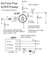
I made a few changes to the schematic that was posted earlier. I realized that the 100 ohm resistor between the high voltage and heater grounds wasn’t doing anything since they are both connected internally to the metal shell and safety ground terminal, so I removed it.

I also lowered the value of the grid leak resistors. With fixed bias (battery grid bias is a form of fixed bias) maximum grid leak values are usually quite a bit lower than when a tube uses cathode bias. The data sheet says max with cathode bias is 1 Meg but gives no specs for fixed bias. I took my cue from the data sheet for a somewhat similar tube, the 6BQ5. It lists 1M for cathode bias and 300k for fixed bias. I’m not sure if this is necessary since the tube isn’t being run as an output tube but I dropped them from 470k to 270k just to be safe.

And the batteries I was using on the breadboard version were almost 6 years old so I ordered some fresh ones and their voltage is just a bit higher. Bias is now at - 25.75v.

If you look at the pic of the breadboarded version you’ll notice I was using common 10w cement wirewound resistors to drop power supply voltage and as plate loads. While 5w parts would have been fine I had the terminal blocks spaced apart so much that I needed to use the longer 10w ones and some of the other tubes I tried needed higher wattages. Here I’m using 5w wirewounds and the black ones used as the plate loads are non-inductive.

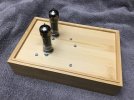
Flow Top.jpg
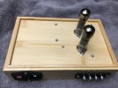
Flow Rear.jpg

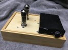
The layout places the tubes off to one side which allows enough space for some Class D amps to sit on top. So the combined footprint of the amp / pre combo is quite small.

Flow w:Nobsound.jpg

Flow w:Douk.jpg
 
Thanks Charlie. This is another great thread and I appreciate your desire to involve those like me who have a lot of interest in building but are without experience and hesitate at the unknown. ;)
 
So I decided to move this from breadboard to build. Once again I’m using a small bamboo box. It was sourced from Amazon and its outside dimensions are 6” x 9”. Most of it is built with solder and normal terminal strips. I decided to keep the breadboard type terminal blocks to mount the output caps. This makes it easier to experiment with different caps if the mood strikes.

View attachment 3499183

I made a few changes to the schematic that was posted earlier. I realized that the 100 ohm resistor between the high voltage and heater grounds wasn’t doing anything since they are both connected internally to the metal shell and safety ground terminal, so I removed it.

I also lowered the value of the grid leak resistors. With fixed bias (battery grid bias is a form of fixed bias) maximum grid leak values are usually quite a bit lower than when a tube uses cathode bias. The data sheet says max with cathode bias is 1 Meg but gives no specs for fixed bias. I took my cue from the data sheet for a somewhat similar tube, the 6BQ5. It lists 1M for cathode bias and 300k for fixed bias. I’m not sure if this is necessary since the tube isn’t being run as an output tube but I dropped them from 470k to 270k just to be safe.

And the batteries I was using on the breadboard version were almost 6 years old so I ordered some fresh ones and their voltage is just a bit higher. Bias is now at - 25.75v.

If you look at the pic of the breadboarded version you’ll notice I was using common 10w cement wirewound resistors to drop power supply voltage and as plate loads. While 5w parts would have been fine I had the terminal blocks spaced apart so much that I needed to use the longer 10w ones and some of the other tubes I tried needed higher wattages. Here I’m using 5w wirewounds and the black ones used as the plate loads are non-inductive.

View attachment 3499190
View attachment 3499191

The layout places the tubes off to one side which allows enough space for some Class D amps to sit on top. So the combined footprint of the amp / pre combo is quite small.

View attachment 3499192

View attachment 3499193
It does look nice and simple!
 
this looks great. can u please post the updated schematic?
Sure . . . here’s the updated schematic. As mentioned, one 100 Ω resistor was eliminated and the 470k grid leak resistors have been changed to 270k. In addition, the value of the carbon comp grid stopper resistors was changed to 430 Ω because that’s what Digi-Key had in stock. The value is not critical but carbon comp is preferred because they are non-inductive. I always add them out of habit but some tube types don’t actually need them.

Flow 6CW5 Pre4D Build.jpg
 
i read earlier you use your amplifier for volume control. ill likely use it with an amp that doesnt have one. what impedance pot/attenuator do you recommend for this, and where is best location for it?
 
i read earlier you use your amplifier for volume control. ill likely use it with an amp that doesnt have one. what impedance pot/attenuator do you recommend for this, and where is best location for it?
While the Class D amps I own do have their own volume controls most all DACs and streamers have remote controlled variable outputs these days. So I control the volume like that and just leave the volume control on the amp set to a position that allows a me to make adjustments on the input side that are fine enough to be practical.

If you don’t have such a device you might want to consider one. Many are quite inexpensive. I do suggest that you have some type of volume control on the input side of the preamp. DAC, streamer or traditional volume pot is up to you.

In some previous tube amp builds I’ve used an audio taper 100k stereo pot on the input. On my Boogie Factor preamp I wanted to have the ability to alter the L/R balance so I used a pair of 100k mono pots on the input. I added a stepped attenuator on the output so I could change the overall volume without altering the channel balance.

More recently I was told that, if you put a pot between the preamp and the amp, that it’s technically better to put it on the amp end of the interconnect rather than on the preamp end. You can also do this with a fixed attenuator (a simple voltage divider) instead of a pot. Some level of attenuation (signal reduction) on the amp end will likely be desirable so that volume adjustments on the input side of the preamp aren't too touchy.

To accomplish this you could mod the amp by adding either a pot (adjustable) or a fixed voltage divider or you could add a fixed attenuator / voltage divider to the amp end of your interconnect instead of modding the amp. These line level fixed attenuators are available commercially but they’re not cheap (~$30 a pair on eBay) considering that you can accomplish the same thing with resistors for a few cents.
 
Here’s a link to the parts at Digi-Key:


The parts list can be customized by anyone who opens the link without changing the original link. So you can add / delete / substitute parts if you like. Digi-Key also has a free shipping option which is discussed here:

http://www.audiokarma.org/forums/in...hipping-on-parts-orders.739513/#post-10018562

Obviously, not all the necessary parts are sold by Digi-Key. You’d have to source the SMPS, tubes, sockets, wire and other hardware elsewhere.

Total cost of this particular build was probably just under $100.
 
Here’s a link to the parts at Digi-Key:


The parts list can be customized by anyone who opens the link without changing the original link. So you can add / delete / substitute parts if you like. Digi-Key also has a free shipping option which is discussed here:

http://www.audiokarma.org/forums/in...hipping-on-parts-orders.739513/#post-10018562

Obviously, not all the necessary parts are sold by Digi-Key. You’d have to source the SMPS, tubes, sockets, wire and other hardware elsewhere.

Total cost of this particular build was probably just under $100.
thanks buddy! just filled my AES cart! got free shiping. gonna add some tube boxes.
 
Back
Top Bottom