• The move to the new server is done. There are some software and database maintenance updates in process. This has us passing the hat around to help out. We appreciate any donations. Seriously, even a dollar helps. The payment page may be found here - https://www.audiokarma.org/support.html

the good, the bad, and the ugly (part II) (Yet another Ampzilla restoration thread)

Cornholio

New favorite google query "site:audiokarma.org"
Hello to the fine folks of AK, and welcome to my second major restoration thread!

Some of you might be familiar with me from my first major restoration thread of similar naming (see: https://audiokarma.org/forums/index...er-dahlquist-dq-10-restoration-thread.910595/) but I am still quite new to the community (and audiophile "stuff" in general, though it's been a long few months since this all started), so if you don't... hi, my name is Joe, I am an engineer based in DC and I like to take on crazy restoration projects like the one I am about to start describing here! (see the thread linked above for a snazzier intro)

So a little bit of background first... to once again shamelessly plug my first thread (there will be a few more, I've got a few things going at the same time) a few months back I set off on a journey to restore (and beautify a little bit) a set of Dahlquist DQ-10 speakers. How I arrived at my selection of those in particular is another story, but what's important here is that soon after beginning that project, I discovered that the DQs are some thirsty beasts, and that the recommended amp would be capable of serving up at least 200wpc. That bit of knowledge hardly narrowed down the selection, so during downtime during that project I accumulated quite a bit of time spent pouring over specs, models, manufacturers, and so forth before arriving at a shortlist of amps (3 in particular, with 2 tied for first) to begin searching for. Chance had it that I found the Ampzilla first, but when I did I jumped at the opportunity and bought it, knowing that it would simply be an addition to my restoration backlog and here we are.

In the same spirit as my first, and still ongoing, restoration thread I am creating this thread to document what will probably be a long, and definitely expensive restoration project (scratch that, already long and quite expensive!), and to hopefully incite the feedback, comments, encouragement, opinions, and discouragement of the wizards that roam the halls of AK. (I have spent a decent amount of time reading here, and you guys/gals actually seem really awesome, which warms my heart, hard thing to find on a very specialized internet forum these days).

Now where this thread mainly differs from my first (aside from the obvious, amp instead of speakers) is that this thread already has quite a bit of catching up to do. I really began this part of my overall vintage hifi restoration project several weeks back, and have already made significant progress, but have been a bit too busy with the DQs and other things, but here I am now, and hopefully once I get things all caught up we can get some conversations going!

Now before I get into what everyone really wants to see (it's always about the nudes, isn't it), I figured a good place to start would be to give a brief rundown of what I (think I) know so far about my 'zilla:

"As-is condition"
  • So the sellers description of what kind of shape she was in was fairly accurate. Their claim was that it had worked for years, then suddenly one day they turned it on and smelled a burning smell, saw a little smoke, and decided she was a goner.
  • That was mostly true, as I will get into later, though there was one important detail missing that might have played a role, might not, it doesn't really matter, what that was is that the Ampzilla had quite clearly been dropped at some point.
  • All in all, not bad shape, and I knew going in that she would require significant work to get running again (which, as you will see later on, I have taken a bit to the extreme)
What I "Know":
  • So unfortunately the unit was missing a serial number, however based on component ages, and assembly quality I believe the unit to be an Ampzilla I that was assembled from a kit, however it is definitely not the original, as the boards have been revised slightly. I do not believe it to be a II though, however I would love it if anyone can help with identification of the exact age/revision (for some reason the designer decided against putting a revision number on the board) though it's not super important, mostly I am just curious.
  • It was definitely assembled from a kit, the build quality could not have come from any reputable factory, and the assembler was not great with a soldering iron!
  • It was the least expensive variant, oh yes, no watt meters or anything. I have yet to find another example out on the web, with the only other photo I have found so far being contained in the original ad/instructions from Popular Electronics magazine. I absolutely challenge you to find another example photo.
  • It is missing the white painted end covers, not a huge deal, I'll just make new ones.

Anyway, without further ado, I present to the AK community the good, the bad, and the ugly, part II: Ampzilla

(I'll be beginning with the first photos I took, and add more as I write more, until I am caught up)

IMG_0805.jpeg IMG_4855.jpeg IMG_7145.jpeg IMG_9943.jpeg IMG_3054.jpeg IMG_1906.jpeg IMG_7523.jpeg
 
Last edited:
Register to hide this ad
Good morning everyone!

I figured I would start the day off right with a post, this time covering initial disassembly of the amp.

002_wire_labels.jpg 004_wire_labels.jpg 005_wire_labels.jpg

So the first step that I took in taking it all apart was to remove/separate all of the wiring, carefully labeling and photographing all connection points and cuts made with heatshrink labels. You may be thinking why do all of that extra work when you have the schematic available? I did so more as a precaution than anything, especially considering how the amp was originally assembled from a kit, it probably wasn't necessary, but there have been projects in the past where I have not done so and regretted it later.

010_wire_labels.jpg 011_wire_labels.jpg 012_wire_labels.jpg 029_amp_cube.jpg 030_amp_cube.jpg 033_fan.jpg 034_fan.jpg

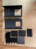
Once the rat's nest of wires was cleared out I removed all of the major subcomponents from the chassis, taking care to bag and label all hardware and to photograph anything that might not seem intuitive later on when I get to reassembly. I started with the monster that is the transformer, and boy oh boy is that thing heavy! Removing the transformer made everything easier as the remaining components were all quite light in comparison. After the transformer went those giant computer grade power caps, followed by the heatsink chimney assembly along with the boards attached.
 
That's the way I do it, strip and start over. I'm in the process converting one of my Ampzilla IIa to an Ampzilla I. Collecting parts as I find them. Can't wait to hear an Ampzilla I. Yours looks to be an intermediate version of Ampzilla I as your output inductor is still on the bottom board but yet different than the 1974 PE article. The later versions of the I had the output inductor on the main drive board. The circuit is still the same, the changes made for mechanical reasons supposedly.

If you do end up having some end panels made I would be interested in 2 sets. Both of my Ampzillas have old beat up rack mount end caps.

If you need any parts let me know.

Craig
 
Last edited:
Good afternoon everyone!

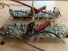
So for this next post following the progress, I disassembled the chimney/heatsink module and removed the boards, separating the main from the lower along the way. If you look closely at the photos I think you might agree with my speculation that this was sold originally as the kit rather than the preassembled unit.

001_pre.jpg 003_pre.jpg 005_main_rem.jpg 006_main_rem.jpg 007_main_rem.jpg 009_small_rem.jpg 011_small_rem.jpg 012_small_rem.jpg
 
Once I was completed with disassembling the chimney and the boards the next step was to clean all of the metal and then begin stripping the boards, this is where the work really began (I'll regain feeling in my fingertips eventually I'm sure!).

022_cleaned_metal.jpg

Cleaning the metal was definitely a messy process, since the assembler used thermal paste quite liberally, however once I found a solvent that worked (denatured alcohol in this case) it was a relatively smooth process, but as usual had to take lots of precautions not to get the paste on anything important as even with the solvent it is tough to clean off of porous surfaces.

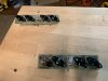
013_main_teardown.jpg 015_main_teardown.jpg 016_main_teardown.jpg 018_main_teardown.jpg 024_the_boards.jpg

With the varying quality of joints, some far overdone, some under, stripping down the boards was a bit more challenging than it typically is for a factory production board where solder is minimized to save costs.

023_the_spread.jpg

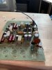
As I had already determined that my unit was a revision from the original from PE, I took care when stripping it to bag and tag every component removed from the boards. Doing so has already paid off, considering that there were several changes discovered between my unit and the original, a few additional parts, a few changes in numbering, and my personal favorite, duplicated use of "C12" on the board (one was supposed to be "C10"). Once the boards were stripped (I tend to do this procedure in stages, the first being trying to get all of the components off with as little heat as possible, followed by removing any solder left, followed finally by cleaning with alcohol to remove any grime and all of the remaining flux) inspection of the bare boards began providing me with quite a lot of information. Perhaps the best detail discovered was which components failed, well, drastically, as was made evident by heat discoloration in the footprints. Additionally, and unfortunately, despite taking greater care than usual in an effort to preserve the boards, there were two areas where I accidentally lost some copper. On the main boards the culprits were where the screws holding the TO-66 transistors were soldered to the boards, and on the lower boards I lost some copper when removing those turrets. In none of the cases is it that bad, at least far from irreparable, and there are several products available out there to choose from for me to repair the boards, however this is where I started to get a few ideas... crazy ideas... I'm an engineer as you may recall, and the more that I looked at these dirt-simple boards the more I started thinking about just.... to be continued!
 
That's the way I do it, strip and start over. I'm in the process converting one of my Ampzilla IIa to an Ampzilla I. Collecting parts as I find them. Can't wait to hear an Ampzilla I. Yours looks to be an intermediate version of Ampzilla I as your output inductor is still on the bottom board but yet different than the 1974 PE article. The later versions of the I had the output inductor on the main drive board. The circuit is still the same, the changes made for mechanical reasons supposedly.

If you do end up having some end panels made I would be interested in 2 sets. Both of my Ampzillas have old beat up rack mount end caps.

If you need any parts let me know.

Craig

Hey Craig,

I will definitely keep you in the loop if I have end panels made, I haven't yet decided whether to find a shop with the right tooling or to make a jig and do it myself, but either way I'll make sure and get at least one extra set for you!

It's funny that you mention that you're converting a IIa to a I, since not two days ago one of my saved searches on the 'bay was triggered by a listing for a pair of original stock, unused Ampzilla IIa boards, needless to say I jumped on the opportunity and they're on their way. (hey... looking at your profile and seeing your location... that wasn't you selling those boards, was it?) That said, I do not plan on doing any conversion to my own unit, but rather I bought the boards for another, very closely related effort that I am currently working on (see "to be continued" above).

As I disassembled everything on my unit I built up some spreadsheets tracking every part that was pulled, cross-referencing the original PE article for additional part requirements since it's mostly the same, and so forth, all the while beginning to spec out replacement components for every part, adjusting values as needed. Anyway, I could go on about the spreadsheets for far longer than any sane person would care to listen, however the point I am making is that for some of the more difficult parts to replace (some of those transistors are quite tough), the one's I won't simply be able to buy from Mouser/Digikey or a specialty shop like PC, I have begun searching for and have made a few good "new old stock" finds. Typically whenever I buy a component that is out of production and I find old inventory (or really any components for the matter) I try to buy way more than I need. That said, I might have parts to share as well. I appreciate your offer as well, I might have to take you up on it!
 
but what's important here is that soon after beginning that project, I discovered that the DQs are some thirsty beasts, and that the recommended amp would be capable of serving up at least 200wpc
yes a sand amp needs big numbers to drive DQ-10s but a good 50 wpc tube amp can do almost everything and sound way better. Does in my case and the sand amp is a McCormack, no slouch at all.

I'll keep following along on this one for those extra touches you seem to throw into projects.
 
Last edited:
The TO-66 and MPSUxx transistors are tough to find especially in any quantity. The big metal Schottky diodes are out there but expensive. The bias IC, CA3046/86, is a bit tough to find also. I have many of these if you need two.

Ampzillas and DQ10s were a hot setup in the 70s.
 
yes a sand amp needs big numbers to drive DQ-10s but a good 50 wpc tube amp can do almost everything and sound way better. Does in my case and the sand amp is a McCormack, no slouch at all.

I'll keep following along on this one for those extra touches you seem to throw into projects.

Hey now... that's getting awfully close to breaking the spirit of the thread by using bad words such as "way better", I'll settle for different, or preferred by some, but unless we're talking Crosley vs. Technics (or Crosley vs. sandpaper, the results are the same) let's try and keep things as they are-- completely and totally subjective! Besides, you should know by now @Blue Shadow that with my taste, there's no way I could afford tubes for this mess. That said, I was originally looking for tubes for at least the preamp, but even that was out of my range. (though in hindsight, I've already spent more than the difference haha)
 
So I've got some updates today, or rather, now is where I will pick up after the to be continued... here's where I left off:

On the main boards the culprits were where the screws holding the TO-66 transistors were soldered to the boards, and on the lower boards I lost some copper when removing those turrets. In none of the cases is it that bad, at least far from irreparable, and there are several products available out there to choose from for me to repair the boards, however this is where I started to get a few ideas... crazy ideas... I'm an engineer as you may recall, and the more that I looked at these dirt-simple boards the more I started thinking about just.... to be continued!

As someone who has quickly grown to appreciate vintage gear, especially G.A.S. products, during my many, many hours of research for this project I felt my heart break just a little each time I stumbled upon a sad story involving blue smoke and a decision that, well, that's all she wrote, with their respective Ampzilla/variant/derivative. Now as I was stripping down the boards, I did make some mistakes, as mentioned in the quote above, that resulted in losing some copper traces from the boards. Now that may be unfortunate, however it's hardly grounds for giving up as there are several known, mostly effective ways of repairing broken traces. That said, none of those ways really "feel right" and they also introduce weak points in the board by default, something that I find quite unacceptable, especially considering the small fortune I am about to drop in rebuilding it all. These thoughts combined with the extra free time of the past few months and a nagging item that has remained on my technical skills backlog for far too long led me to make the decision that I finally had a valid reason to justify putting in the hours to teach myself Eagle CAD. Although I would argue that PCB CAD was far easier to learn than traditional 3D modeling CAD, over the past few weeks I invested easily over 100 hours following tutorials, learning the ins and outs of the software, and preparing to do the unthinkable: to reverse-engineer and clone the boards.

Now I know what many of you are already thinking: why would you do any reverse engineering when you can just go off of the kit instructions, schematic, layout. Well, there are a few reasons. For starters, my Ampzilla was a revision, still unknown which revision, but a revision upon the original Ampzilla from the PE article, and because of that I wanted to stick with my version to keep it the same. Beyond that, well, my boards aren't the same as the ones from the original kit, and I would have to build the kit in Eagle anyway, which would have been somewhat difficult because the only copies I have found that show the layout are very rough, often photographs of bent and ruffled pages from the PE article, and if I want this to be a legit Ampzilla I need more than a fuzzy image, I need precise dimensions and parts placement, which is something I just don't have for the original kit. Nevertheless, in my journey to learn Eagle, the first place I did start was by building out the schematic from the PE article in Eagle as an exercise, shown below:

Screen Shot 2020-07-17 at 9.01.30 PM.png

Once I had completed the schematic from the PE article and familiarized myself with doing board layouts in Eagle, I next moved on to my version, where I do have in hand two original main PCBs (actually 4 now, as I snagged a pair of new old stock Ampzilla IIa boards off the 'bay last week, but that's for later discussion). Initially I started by taking the schematic from the original kit and trying to modify it for the changes made in my Ampzilla's revision, but I quickly found myself continuously getting lost and missing things, and since this is a learning opportunity I ended up scrapping that plan and doing an old fashioned reverse engineering direct from the absolute truth: the boards themselves. This proved to be a useful exercise, as some of the changes between the original and this version were subtle, and the way in which the solder turrets and transistors were laid out and labeled in the original schematic would have made for a lot of confusion, as they did not match the physical layout of my board, in the end the product, as seen below, was the schematic:

Screen Shot 2020-07-17 at 9.04.41 PM.png

Now if you're familiar with Eagle CAD you might be thinking to yourself "so what, you learned the basics, throwing together those boards is no great task at all, this is far from impressive", and you know what, it's not that impressive, but... and this is a big but... things change altogether once you decide that you don't just want a replication of a circuit, that you want the same parts in the same positions with the same holes in the same locations from a board that was made well before Eagle CAD existed, AND, here's the kicker: the board designer did not adhere to, at least not strictly, any consistent grid system, everything on the board is a mix of traditional 1/10th inch grid measurements, imperial units (1/4", 1/2", and so forth), AND metric units in a few cases. The board designer also apparently did not follow the standard of setting the origins (0,0) at the lower left corner as most do but rather, as I deduced, seems to have set the board center (the spot from which all other components are laid out relative to) using R28 and one jumper. Furthermore, because of the bizarre switching of units and sometimes using grid units, sometimes not, and the fact that it was designed for components readily available in the mid 70s meant that for each component I had to custom build it's footprint using a small ruler and a micrometer. Taking it one step further, there was clearly a lot of inconsistency between boards (my left and right channel are proof enough) that in doing all of the measuring I had to make a determination for dimensions not based on actual measurements, but rather by extrapolating design intent through a combination of rounding, and cross-referencing relative pin locations. I could ramble on and on about this for hours, but in a nutshell: it was a blast to do it all, 10/10 would do it again, and today I finished the first complete draft of the main boards (still have to do the satellites/lower boards) as you can see below:

Screen Shot 2020-07-17 at 8.44.28 PM.png Screen Shot 2020-07-17 at 8.44.08 PM.png

At this point I have so much more to say, however my hands grow weary, so I will save it for next time, however with that said, I would like to leave everyone with a little something to chew on:
  • Once I have completed the boards, I will generate build files that I will send to a PCB house to have made for me, something that once you have the files perfect can be done over and over again, in whatever quantity, color, copper weight, etc that you want. I am curious as to whether or not this might be something others in the community would be interested in learning.
  • Once you have these boards, you essentially have a complete Ampzilla, save for maybe finding a good source for a closely matching transformer. The remainder of the components can be purchased, with the exception of the chassis. With that in mind, the chassis, including the heat sinks, is of an extremely simple design, one that, as part of this process, I fully intend to model in regular 3D CAD. In fact, the design is so simple that it would not be terribly expensive at all to find a metal shop willing to reproduce parts, especially not if the quantity is high enough.
  • One aspect of this process so far that I have enjoyed is the archival nature of capturing all of this information in a modern form, and once I have completed the boards for my 'Zilla, I then plan to do the same for the IIa boards I have, and heck why stop there, so if you happen to have, or know someone who might have, any old boards, no matter the condition, that they would be either willing to sell to me, or loan to me for a few weeks, do reach out.
  • Finally, what are all your thoughts on the prospect of say, someone recreating and making available, a brand new 'Zilla kit in 2020, either with or without components and only very slight design modifications as required for parts that are no longer produced to be replaced by modern readily available components? If you can believe it, at this point I have already generated roughly 75% of all the necessary files to make this happen. Share your thoughts please!
 
Last edited:
How did you remove the old turrets without destroying the traces? I have some turrets I need to replace, solder wick and a drill come to mind.

Craig
 
How did you remove the old turrets without destroying the traces? I have some turrets I need to replace, solder wick and a drill come to mind.

Craig

On the main boards it was as simple as using a manual solder vac/wick to remove as much as possible, then drilling them out. The fact that the turrets are on the opposite side of the board as the traces made these easy to remove.

On the output boards it was a whole different story... I unfortunately tore up several traces before getting the technique down. A lot of it really comes down to how much solder was used and how much of it managed to find its way under the base of the turret. Getting the hang of it really came down to basically doing the same thing, vac/wick to remove as much of the solder as possible, then drilling out, just doing it slower. After the first few pulled up traces I did try using a slightly larger diameter drill and also trying to drill beyond just removing the crimped ring (drilling straight through) but despite intuition telling me that it should help it really introduced more new challenges that made it even more difficult to do without tearing traces. The only real tip I have that did work for me is to drill a little bit further (but not all the way through, maybe half the thickness of the board), drilling before you desolder (crucial), then, while in the process of desoldering, melt the surrounding solder and while it is liquid use a pair of needle nose pliers to lever the turret in one direction slightly, not too far, just enough so that the edge of the base of the turret opposite the direction you levered it will break free, but the turret overall remains attached. Doing this repeatedly in enough directions to cover the complete perimeter of the turret base, prior to desoldering, made for a clean removal without pulling up the traces in most cases, but still not all. Also make sure that you use a sharp drill, and don't apply any additional downward force while drilling. If your bit is dull or you push down too hard, aside from the risk of pushing the turret through complete with the trace you risk deforming the turret at the point where the drill is in contact, this deformation will form a concave depression where the drilling occurred with edges that are greater in diameter than the turret was originally, effectively creating a lip that is all but guaranteed to take the trace with it.
 
I've probably staked 25,000 turrets building gheetar amps but never had to remove any that were soldered to traces. I'm also going to try and figure out a way connect the large B+/- wires to the board, connecting 14/16ga wire to a tiny turret doesn't do it for me. The amplifier output/gnd turrets need some rethinking too.
 
Last edited:
I've probably staked 25,000 turrets building gheetar amps but never had to remove any that were soldered to traces. I'm also going to try and figure out a way connect the large B+/- wires to the board, connecting 14/16ga wire to a tiny turret doesn't do it for me. The amplifier output/gnd turrets needs some rethinking too.
Since I finished the board designs for the unchanged original boards I have created a few variations. I have a variation that reconfigures the traces for Q1-Q6, Q8 which originally used transistors that for some odd reason had a EBC pinout instead of a ECB pinout such that they now accept ECB transistors like the MJE243G/MJE253G. I have another variation that replaces the jumpers with vias and puts the copper on the top layer. I created another variation that combines the two boards into one but leaves all the geometry the same and does not connect the two electrically, along with a version that does. As far as I can deduce from reverse engineering it all the only reason for having the boards separate is if you only have the one layer to work with since the output board has to be flipped such that the big TO-3 transistors can be mounted directly to the heatsink. In all of the variations I have created so far though, one thing has remained certain, if the design isn't exactly replicating the board, then bye bye turrets. Quite simply, there are just so many empirically better ways to make connections to boards or between them than turrets, and the idea that you're just wrapping some wire around two of them for a connection just makes me cringe as an engineer, because even with a dab of solder at the wrap you're never going to have repeatable results. I could go on and on but I'll leave it at that. Pending I have any of the variation boards made, when I get to deciding how to handle wire to board connections I'll definitely discuss it here!
 
The later versions, II and IIa, used plug-in edge connectors but sadly those connectors are NLA. If not using plug-in connectors the top to bottom board connection needs to be flexible so as to be able to service the top board without having to remove the bottom board. Then again you don't want to rely on the traces as the sole mechanical connection either. What to do?

Craig
 
Another problem using modern/available parts on the old PCB layout, on the TO-66s sometimes both screws were used, sometimes only one was used for connections. Changing to TO-220 style will need jumpers to connect the screws on a few of them. I've had to do this on the IIa boards and some SAE 2400 and MKIIIC boards.

Craig
 
Back
Top Bottom