

You are using an out of date browser. It may not display this or other websites correctly.
You should upgrade or use an alternative browser.
You should upgrade or use an alternative browser.
the good, the bad, and the ugly (part II) (Yet another Ampzilla restoration thread)

Cornholio
New favorite google query "site:audiokarma.org"
Well, I hope I can resurrect this thread, I may have been silent for a while, but I certainly haven't been idle!
Over the past few months I have been steadily preparing, designing, and ordering parts. Once I had all of the parts on hand, I ordered the boards to be manufactured, received the boards, did some more planning, circuit equivalency testing, more planning, a few extra parts orders, then, and finally then, the real fun began, the build. I started the build at the beginning of February, and while I was meticulous about every last detail (x4), which made the build last several weeks, it was also delayed by a minor, but urgent surgery. Over this past weekend I began testing, and I am currently in the initial listening tests phase. In the next several posts I will be documenting the build process, so stay tuned!
Notes:

Over the past few months I have been steadily preparing, designing, and ordering parts. Once I had all of the parts on hand, I ordered the boards to be manufactured, received the boards, did some more planning, circuit equivalency testing, more planning, a few extra parts orders, then, and finally then, the real fun began, the build. I started the build at the beginning of February, and while I was meticulous about every last detail (x4), which made the build last several weeks, it was also delayed by a minor, but urgent surgery. Over this past weekend I began testing, and I am currently in the initial listening tests phase. In the next several posts I will be documenting the build process, so stay tuned!
Notes:
- Although I did redesign the boards and layouts, (before redesigning, I began by digitally recreating the original boards, just in case I ever wanted to convert these to new "stock" board models) the circuit is electrically identical.
- I rebuilt two Ampzilla I units, yes, two, why two? An offer I couldn't pass up on presented itself last fall getting me a second parts-only unit with the meters, so I decided that I would sentence myself to twice the labor and cost!
- I built both at the same time, and wherever possible matched components across all four driver boards. Essentially a matched pair. I am thinking of biamplifying or using each as a monoblock.
- The first unit I obtained was an older model, and a bit unusual in that it is still the only example I have been able to find of a unit without the meters. I have scoured the internet, and have yet to find a photo or drawing of an Ampzilla I without the meters.
- The second unit I obtained was a later model, I believe it to be the version that was produced in the largest numbers (correct me if I am wrong and you're reading this, Craig). I based the circuit off of the boards in this unit 790001/790003.
Cornholio
New favorite google query "site:audiokarma.org"
So before I begin, I have a confession: I didn't follow the instructions in order. There, I said it. Having said it, though, I am going to more or less follow the order of the original build instructions.
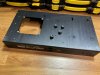
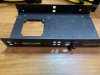
Beginning with the chassis...
I installed the feet. I did replace the feet on both units, not because anything was wrong with the ones they came with, in fact they were all in pretty good shape and were the same on both units, but because I can't stand hard plastic feet, especially on a piece of equipment as heavy as these Ampzillas. So the feet I ended up buying as replacements were admittedly a bit softer than I was anticipating, so as a result I had to clamp down pretty far on each of them in order to stiffen them up enough so that the mounting screws couldn't easily gouge into the surface on which the unit is placed. Doing this gave the feet a bit more of an "organic" shape, however it is consistent on both units, I think it looks cool, and best of all it gives each 40+ pound hunk of steel and aluminum a certain grippy purchase on the surface below that inspires confidence.
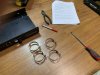
Then came the filter caps which I replaced, along with the clamps that I did not. Somewhere along the way I popped in the speaker and main power fuseholders. Beyond that, I followed the original instructions.



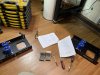

Beginning with the chassis...
I installed the feet. I did replace the feet on both units, not because anything was wrong with the ones they came with, in fact they were all in pretty good shape and were the same on both units, but because I can't stand hard plastic feet, especially on a piece of equipment as heavy as these Ampzillas. So the feet I ended up buying as replacements were admittedly a bit softer than I was anticipating, so as a result I had to clamp down pretty far on each of them in order to stiffen them up enough so that the mounting screws couldn't easily gouge into the surface on which the unit is placed. Doing this gave the feet a bit more of an "organic" shape, however it is consistent on both units, I think it looks cool, and best of all it gives each 40+ pound hunk of steel and aluminum a certain grippy purchase on the surface below that inspires confidence.
Then came the filter caps which I replaced, along with the clamps that I did not. Somewhere along the way I popped in the speaker and main power fuseholders. Beyond that, I followed the original instructions.
Cornholio
New favorite google query "site:audiokarma.org"
Personally, I think it would be boring if I simply reiterated the original build instructions, so for that reason I am going to put a little bit more effort towards describing changes or modifications that I made, beginning with power input.
I am an engineer, and I will admit, when working on projects like this especially, I am a bit of a control freak-- beyond a certain level of financial, time, and emotional investment in the project things sort of devolved into it will be exactly as I want it to be, without exception, except when limited by obvious things like power ratings, etc. and I absolutely hate fixed power cords. I get it, vintage equipment, back then they either didn't have the IEC standards or it just wasn't common practice to use removable power cords, but I also can't stand it, and have pledged to myself that if I am going to do any work on a piece of vintage equipment then it must include converting to IEC plugs/sockets if it already has not been done. I am aware of every single pro and con to doing this, trust me, I obsessed over this for a few weeks. I am also a fan of making my own power cords with quality connectors, not because I believe in any snake oil nonsense, but rather because of the added benefit of getting to decide exactly how long the cord will be, but this is really just a bonus. I also cringe at the idea of cutting significant amount of original chassis sheet metal (except enlarging existing holes, I am pretty liberal about that, especially when it is filled by jewelry that is clearly overkill), and the idea of IEC C13/14 pigtails hanging out of chassis is likewise unacceptable. So this is what I came up with:
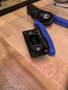
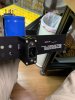

In obsessing over the dilemma of cut the chassis or not I discovered that I am not the only person with this concern, there are a lot of folks out there with this same problem I found. Here's my solution: a compact box that secures itself to the chassis non-destructively using only the existing opening for both mounting and feeding wires through. The bracket really clamps down tight, too, this thing isn't going anywhere. For a brief moment I thought about trying to patent it (assuming that no one has done so already) and produce and sell it as a product with interchangeable endplates matched to specific vintage models, but only for a brief moment, before saying to myself "wait, no, f%$K that, totally not in the spirit of this", so here it is if it doesn't exist elsewhere, free and openly available for all to make, which is way easier to do than you might think, at most requiring only one extra tool (the little file set from HF worked well enough for me), the purchase of some inexpensive drill bits, all of this assuming that you have a drill (my drill press currently resides with my brother, several hundred miles north of me, I was able to do it easily with a compact cordless drill).
With that said, I think a full tutorial will live in its own independent thread, once I get around to it. In a nutshell, it'll realistically cost you less than $30 to order everything (including spares, definitely order a few, they're cheap) and about an hour to make.
Moving on, those are on both units now, as well as my pre-amp (Bryston 1B), and inevitably one will end up on both the Bryston 3B, which I am salivating over working on soon, as well as the DQ-LP1 crossover.
I am an engineer, and I will admit, when working on projects like this especially, I am a bit of a control freak-- beyond a certain level of financial, time, and emotional investment in the project things sort of devolved into it will be exactly as I want it to be, without exception, except when limited by obvious things like power ratings, etc. and I absolutely hate fixed power cords. I get it, vintage equipment, back then they either didn't have the IEC standards or it just wasn't common practice to use removable power cords, but I also can't stand it, and have pledged to myself that if I am going to do any work on a piece of vintage equipment then it must include converting to IEC plugs/sockets if it already has not been done. I am aware of every single pro and con to doing this, trust me, I obsessed over this for a few weeks. I am also a fan of making my own power cords with quality connectors, not because I believe in any snake oil nonsense, but rather because of the added benefit of getting to decide exactly how long the cord will be, but this is really just a bonus. I also cringe at the idea of cutting significant amount of original chassis sheet metal (except enlarging existing holes, I am pretty liberal about that, especially when it is filled by jewelry that is clearly overkill), and the idea of IEC C13/14 pigtails hanging out of chassis is likewise unacceptable. So this is what I came up with:
In obsessing over the dilemma of cut the chassis or not I discovered that I am not the only person with this concern, there are a lot of folks out there with this same problem I found. Here's my solution: a compact box that secures itself to the chassis non-destructively using only the existing opening for both mounting and feeding wires through. The bracket really clamps down tight, too, this thing isn't going anywhere. For a brief moment I thought about trying to patent it (assuming that no one has done so already) and produce and sell it as a product with interchangeable endplates matched to specific vintage models, but only for a brief moment, before saying to myself "wait, no, f%$K that, totally not in the spirit of this", so here it is if it doesn't exist elsewhere, free and openly available for all to make, which is way easier to do than you might think, at most requiring only one extra tool (the little file set from HF worked well enough for me), the purchase of some inexpensive drill bits, all of this assuming that you have a drill (my drill press currently resides with my brother, several hundred miles north of me, I was able to do it easily with a compact cordless drill).
With that said, I think a full tutorial will live in its own independent thread, once I get around to it. In a nutshell, it'll realistically cost you less than $30 to order everything (including spares, definitely order a few, they're cheap) and about an hour to make.
Moving on, those are on both units now, as well as my pre-amp (Bryston 1B), and inevitably one will end up on both the Bryston 3B, which I am salivating over working on soon, as well as the DQ-LP1 crossover.
Cornholio
New favorite google query "site:audiokarma.org"
So I have to start this post with yet another confession... while I denounce snake oil, and cannot take seriously the words of those who advocate for it, I am embarrassed to say that my Venn diagram circle tends to overlap with theirs when it comes to one thing: connectors (okay, capacitors too, but only to the mildest degree). In the next few photos you will find what I have been affectionately referring to as Ampzilla's "jewelry":
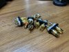
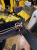

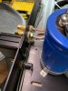
I offer no further justifications or arguments regarding this, judge as you will, and note that nearly everything that could be viewed or deemed to be "excessive" in this build was made in America, a conscious choice (and a shameless excuse).
Next came the fun process of harnessing the units.
As you might have guessed, I replaced all of the original wire (and I mean all of it, an upcoming post will show). I did briefly consider the fancy brands, but after performing a cost to benefit analysis comparing several options (sadly, literally), while I might have bought fancy connectors from some of the "boutique" type manufacturers, I drew a hard line at wire from those same manufacturers, I can't buy into that. Long story short, I couldn't just put any old wire in there, so after some research that only included scientifically accurate statements I settled on a nice middle ground: mil-spec 16878/4 or 22759/11 silver plated copper PTFE (teflon) insulated wire. Sure it's a bit stiff, and working with it takes a bit of getting used to, and it isn't exactly cheap, in fact it's quite expensive, making buying by the roll prohibitively expensive and there are very few places selling short lengths of it (far fewer now, as I basically wiped out half of the stock available of short lengths in the US last month, seriously), but it's nice stuff, and since it is governed under a standard you know what you're getting every time you buy it.
So after several months of thinking about it and researching it the chassis/hookup wire dilemma was over, but only to be replaced by one of the most difficult parts of the entire project: internal connectors. I honestly don't want to talk about it, too soon, but I am strongly opposed to soldering wires to boards and the like. I prefer connectors whenever and wherever possible. But not just any connectors, I needed to use the right connectors, designed for the right purpose, with the right parameters, sized such that both wire and insulation diameter was taken into account, and for 95% of it all, must be crimped on. Crimping is king. This made for an extremely tedious job of spec'ing out every single connection point in the amp, individually, until I could find a compatible connector. It gets worse though, there were often multiple options, and a lot of cross compatibility, so the problem becomes here, as in any other harnessing project, how to buy the fewest varieties of connector that will be compatible in every parameter to cover all 40 or 50 individual connection points in the amplifier in order to make it affordable. Oh, and did I mention that you also best make sure that you have or can affordably obtain compatible tooling to do the install with otherwise you would be far better off just soldering to the board. I am making it sound worse than it actually is, sure building BOMs can be a complicated process, but having rules, and most of all, discipline, makes it doable. I do it because it's what I have been trained to do. And it really isn't that bad, and the benefits far outweigh the unpleasantness. By a lot. In fact, with the level of depth I got into with this project (one of my goals was and still is, to have reverse engineered the entire amplifier and provide that information for others to use to build the kit), it's the only way to do it, track everything. Anyways, I made custom harness using the wire and connectors I just ranted about, also, I bumped all the 14 AWG wire up to 12 AWG, just because, and as precisely as possible symmetrically matched both sides of the harness. And then I was about 75% done with the harnessing, the rest had to wait until the boards were ready.
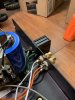
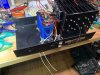
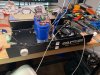

That's all for tonight, more to come tomorrow.
I offer no further justifications or arguments regarding this, judge as you will, and note that nearly everything that could be viewed or deemed to be "excessive" in this build was made in America, a conscious choice (and a shameless excuse).
Next came the fun process of harnessing the units.
As you might have guessed, I replaced all of the original wire (and I mean all of it, an upcoming post will show). I did briefly consider the fancy brands, but after performing a cost to benefit analysis comparing several options (sadly, literally), while I might have bought fancy connectors from some of the "boutique" type manufacturers, I drew a hard line at wire from those same manufacturers, I can't buy into that. Long story short, I couldn't just put any old wire in there, so after some research that only included scientifically accurate statements I settled on a nice middle ground: mil-spec 16878/4 or 22759/11 silver plated copper PTFE (teflon) insulated wire. Sure it's a bit stiff, and working with it takes a bit of getting used to, and it isn't exactly cheap, in fact it's quite expensive, making buying by the roll prohibitively expensive and there are very few places selling short lengths of it (far fewer now, as I basically wiped out half of the stock available of short lengths in the US last month, seriously), but it's nice stuff, and since it is governed under a standard you know what you're getting every time you buy it.
So after several months of thinking about it and researching it the chassis/hookup wire dilemma was over, but only to be replaced by one of the most difficult parts of the entire project: internal connectors. I honestly don't want to talk about it, too soon, but I am strongly opposed to soldering wires to boards and the like. I prefer connectors whenever and wherever possible. But not just any connectors, I needed to use the right connectors, designed for the right purpose, with the right parameters, sized such that both wire and insulation diameter was taken into account, and for 95% of it all, must be crimped on. Crimping is king. This made for an extremely tedious job of spec'ing out every single connection point in the amp, individually, until I could find a compatible connector. It gets worse though, there were often multiple options, and a lot of cross compatibility, so the problem becomes here, as in any other harnessing project, how to buy the fewest varieties of connector that will be compatible in every parameter to cover all 40 or 50 individual connection points in the amplifier in order to make it affordable. Oh, and did I mention that you also best make sure that you have or can affordably obtain compatible tooling to do the install with otherwise you would be far better off just soldering to the board. I am making it sound worse than it actually is, sure building BOMs can be a complicated process, but having rules, and most of all, discipline, makes it doable. I do it because it's what I have been trained to do. And it really isn't that bad, and the benefits far outweigh the unpleasantness. By a lot. In fact, with the level of depth I got into with this project (one of my goals was and still is, to have reverse engineered the entire amplifier and provide that information for others to use to build the kit), it's the only way to do it, track everything. Anyways, I made custom harness using the wire and connectors I just ranted about, also, I bumped all the 14 AWG wire up to 12 AWG, just because, and as precisely as possible symmetrically matched both sides of the harness. And then I was about 75% done with the harnessing, the rest had to wait until the boards were ready.
That's all for tonight, more to come tomorrow.
Cornholio
New favorite google query "site:audiokarma.org"
So in my last post, when I said I replaced all of the internal wiring, I sure did mean literally all of it, and that included the transformer wiring!
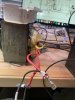
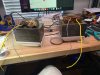
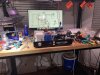
While a transformer is normally something I wouldn't touch--simply clean it off, maybe re-terminate the wires, and reinstall--the one I pulled out of the older of the two units was showing some signs that the integrity of the existing wiring, and its insulation, was not something that I could trust. Sure enough, I opened her up and found cracked insulation in several spots along the secondary coil outputs on portions of the wiring typically obscured by the transformer end bells. Following the strict rule of everything done to one unit must be done on both I opened up both transformers and did a little bit of work. First, I had to get better access to the wires as close to where the coils were tapped as possible, which consisted of temporarily removing the paper insulators and permanently removing old tape as it basically removed itself. Once I was able to get as close as I thought I could get I trimmed off the original wires and spliced in new mil-spec wires in their place (note: used multiple layers of special, extra thick, adhesive lined, which of course only stuck to the old wires since teflon doesn't stick to much, high temp heat shrink insulation to protect the splices). I then cleaned everything up and rewrapped the ends and paper insulators with fresh high temp tape (I love that stuff, especially for soldering) and installed, photos below, enjoy!


While a transformer is normally something I wouldn't touch--simply clean it off, maybe re-terminate the wires, and reinstall--the one I pulled out of the older of the two units was showing some signs that the integrity of the existing wiring, and its insulation, was not something that I could trust. Sure enough, I opened her up and found cracked insulation in several spots along the secondary coil outputs on portions of the wiring typically obscured by the transformer end bells. Following the strict rule of everything done to one unit must be done on both I opened up both transformers and did a little bit of work. First, I had to get better access to the wires as close to where the coils were tapped as possible, which consisted of temporarily removing the paper insulators and permanently removing old tape as it basically removed itself. Once I was able to get as close as I thought I could get I trimmed off the original wires and spliced in new mil-spec wires in their place (note: used multiple layers of special, extra thick, adhesive lined, which of course only stuck to the old wires since teflon doesn't stick to much, high temp heat shrink insulation to protect the splices). I then cleaned everything up and rewrapped the ends and paper insulators with fresh high temp tape (I love that stuff, especially for soldering) and installed, photos below, enjoy!
Cornholio
New favorite google query "site:audiokarma.org"
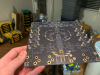
...which finally brings us to the boards themselves.
I could go on for pages and pages about the boards and the redesign, but I'll save that for later, instead focusing on the assembly process and changes I made, beginning with the studs for mounting the TO-66 transistors, at least on the original boards, as these have all been replaced in my build with TO-220 packaged transistors since new replacement metal case TO-66s are unobtainium. In the original design these studs were created by soldering the screw caps directly to the board, which totally works, but it irked me, perhaps it was the fact that you're using a non-electronic component to do a component's job, or maybe it was the fact that they were made of steel, either way they looked unprofessional if nothing else and had to go. With that said, whatever I chose as the replacement had to also perform the function of mounting the boards to the small L-shaped heat sinks, and another design rule I made was that the finished product needed to be a drop-in replacement, so after some research I decided to replace the soldered screws with what I would call the correct part for the job: PEM (like the nuts) press fit PCB studs. Unlike the original steel screws, these studs are made of plated copper, and were purpose-designed for use in PCB applications. Since I wanted to forgo the design in which the solder was the only mechanical connection to the boards I decided to go with press-fit, but solderable studs. There were other options available, including non-press-fit solder only studs, or even studs that could be press fitted into plated through holes in the PCB (definitely going to look into these for future versions) that don't require solder at all, but I preferred the idea of being able to separate the responsibilities of the part into mechanical connection and electrical connection and went for it. There were a few caveats and lessons learned, these included:


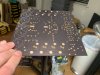
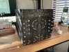

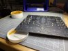
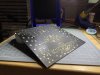
I could go on for pages and pages about the boards and the redesign, but I'll save that for later, instead focusing on the assembly process and changes I made, beginning with the studs for mounting the TO-66 transistors, at least on the original boards, as these have all been replaced in my build with TO-220 packaged transistors since new replacement metal case TO-66s are unobtainium. In the original design these studs were created by soldering the screw caps directly to the board, which totally works, but it irked me, perhaps it was the fact that you're using a non-electronic component to do a component's job, or maybe it was the fact that they were made of steel, either way they looked unprofessional if nothing else and had to go. With that said, whatever I chose as the replacement had to also perform the function of mounting the boards to the small L-shaped heat sinks, and another design rule I made was that the finished product needed to be a drop-in replacement, so after some research I decided to replace the soldered screws with what I would call the correct part for the job: PEM (like the nuts) press fit PCB studs. Unlike the original steel screws, these studs are made of plated copper, and were purpose-designed for use in PCB applications. Since I wanted to forgo the design in which the solder was the only mechanical connection to the boards I decided to go with press-fit, but solderable studs. There were other options available, including non-press-fit solder only studs, or even studs that could be press fitted into plated through holes in the PCB (definitely going to look into these for future versions) that don't require solder at all, but I preferred the idea of being able to separate the responsibilities of the part into mechanical connection and electrical connection and went for it. There were a few caveats and lessons learned, these included:
- needing an arbor press in order to install the studs (oh no, an excuse to buy a tool that I can use for numerous other things!)
- needing not just the press, but a suitably sized die. I managed to snag the correct one for a fair price off of the bay, however if my drill press wasn't on loan right now it would have been easy to make one.
- PCB manufacturers are a bit weird about non-plated through holes, so the design had to call for decent tolerances, and a minimum gap between the edge of the hole and the surrounding pad, fortunately I did my research and studied the specifications so this wasn't a problem and the holes turned out perfect.
- Copper hardware is fragile, I only accidentally sheared off one stud, but it was enough to make me super careful to not do it again. Luckily I only removed a tiny bit of the pad trace when popping out the broken one and it was on the side that didn't matter.
- You still have to solder the studs, and the coating applied by the manufacturer made adhesion super easy, too easy, in fact. When hot solder hits these studs and the stud is hot enough for adhesion, you best be careful, because it will quickly spread to cover as much surface area of the stud as possible, resulting in jammed up threads and a fair amount of tedious rework. In the future I will be using peel-off solder resist on these.
Cornholio
New favorite google query "site:audiokarma.org"
Once I had the press fit studs installed and soldered to all four driver boards, next came the pin sockets for the would-be TO-66 transistors. Pin sockets? What pin sockets? Well...
As I knew that the likelihood of locating new TO-66 transistors was going to be low, and with there being a few (well, at least two) possible TO-220 replacement options, paired with my reluctance to use both mechanical fastening and solder on the same component, I decided that I wanted the smaller transistors to be just as easy to remove and swap as the big output transistors. After some research, and much tedious data sheet reading, I was able to locate easily obtainable PCB pin sockets that met or exceeded all required ratings and could accept both rectangular and round pin contacts.
These were pretty straightforward to install--drop 'em in the holes and solder--though they did cause a slight bit of trouble in one of the same ways that I neglected to mention in the previous post as the studs: solder flow. Specifically, despite sizing the through holes per manufacturer specs, solder applied on one side of the board was easily flowing through the hole and soldering both sides at the same time. On one hand, this was great once I got the hang of it, as you could cleanly solder both sides at the same time, on the other hand getting the hang of it was tricky and required basically watching both sides of the board at the same time and monitoring how much solder was applied to the joint closely. In short, if it felt like it was taking too much solder to create the joint then it probably was, and was making a mess on the other side of the board. The solution was simple though, by kicking the temperature of the iron tip up a few notches, flow between the two sides was increased, however it also meant that the solder would more easily propagate on its own to the places where it was supposed to be. Check out the photos below to see how things turned out, and note the use of the heat tape, I love that stuff.
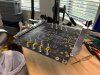
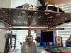

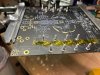
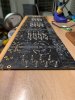

As I knew that the likelihood of locating new TO-66 transistors was going to be low, and with there being a few (well, at least two) possible TO-220 replacement options, paired with my reluctance to use both mechanical fastening and solder on the same component, I decided that I wanted the smaller transistors to be just as easy to remove and swap as the big output transistors. After some research, and much tedious data sheet reading, I was able to locate easily obtainable PCB pin sockets that met or exceeded all required ratings and could accept both rectangular and round pin contacts.
These were pretty straightforward to install--drop 'em in the holes and solder--though they did cause a slight bit of trouble in one of the same ways that I neglected to mention in the previous post as the studs: solder flow. Specifically, despite sizing the through holes per manufacturer specs, solder applied on one side of the board was easily flowing through the hole and soldering both sides at the same time. On one hand, this was great once I got the hang of it, as you could cleanly solder both sides at the same time, on the other hand getting the hang of it was tricky and required basically watching both sides of the board at the same time and monitoring how much solder was applied to the joint closely. In short, if it felt like it was taking too much solder to create the joint then it probably was, and was making a mess on the other side of the board. The solution was simple though, by kicking the temperature of the iron tip up a few notches, flow between the two sides was increased, however it also meant that the solder would more easily propagate on its own to the places where it was supposed to be. Check out the photos below to see how things turned out, and note the use of the heat tape, I love that stuff.
Cornholio
New favorite google query "site:audiokarma.org"
Following the pin sockets were the remaining board mounted connectors, instead of turrets (not a fan) I opted to use solder on stud connectors for power, and outputs, and a SMB connector for signal in. For future iterations on the design these are components that I will be looking into press fit alternatives, especially with the amount of heat required for soldering on the four pin studs I used.
I should note that in general I populated the boards in the order of most heat required to least heat tolerant.
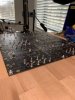
I should note that in general I populated the boards in the order of most heat required to least heat tolerant.
Cornholio
New favorite google query "site:audiokarma.org"
Once all of the PCB connectors were attached, the last remaining heat sink, I mean high heat part to go on the boards were the output coils. Initially I had planned on simply reusing these from the old boards as there's nothing to go bad in a simple copper coil, but that plan changed when I bought an LCR meter and realized that the pairs from each original board set were non-negligibly different in value from each other, not to mention the ones from the newer of the two units had significantly longer leads that were folded over. That left me with one option: make new ones.
After some research, obtaining the proper magnet wire, and a bit of experimentation, I was able to fashion a tool from an old wooden spool and the handle of an exacto knife that was just the right size to match the diameter of the originals I made new coils, matching them all to the greatest precision the LCR meter provided, and installed them on the boards. I did follow the same concept as the newer original boards, in which the leads for the coils are a bit longer and folded over before soldering on the underside of the boards, however I made it a much cleaner joint with elongated pads specifically for the purpose instead of a large patch of exposed copper.


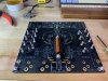
After some research, obtaining the proper magnet wire, and a bit of experimentation, I was able to fashion a tool from an old wooden spool and the handle of an exacto knife that was just the right size to match the diameter of the originals I made new coils, matching them all to the greatest precision the LCR meter provided, and installed them on the boards. I did follow the same concept as the newer original boards, in which the leads for the coils are a bit longer and folded over before soldering on the underside of the boards, however I made it a much cleaner joint with elongated pads specifically for the purpose instead of a large patch of exposed copper.
Cornholio
New favorite google query "site:audiokarma.org"
Once all of the high heat parts were on the boards I installed the rest of the components in the order instructed in the original kit. Although the full assembly of the boards took about a week, I didn't stop to take many photos, I was far too focused on repeatability/consistency, matching components, and clean joints. After every few components installed I would stop and use a solvent to remove the excess flux from the boards, as it would quickly become necessary. This is due in part to the fact that not only was I applying flux paste, but also using a flux core solder (Cardas Quad Eutectic, to be precise, passes my "good stuff" test for sure), often erring on the side of too much, but using flux really does make everything cleaner and easier, even if using a flux core solder. Although I have a fancy "helping hands" tool with the positionable arms, I hardly used it, instead favoring the use of heat tape.
You might notice that somewhere along the way the output transistor sockets were installed... don't get me started on TO-3 sockets. Everything about these sockets was a huge p.i.t.a. from alignment, to the fact that they are ridiculously expensive. I followed the same strategy as the original boards in terms of hole placement and sizing, requiring that the tabs be carefully bent and that you use a metric ton of solder for each joint, even though I didn't need to. Determining the dimensions and hole spacing for these boards so that they could drop in without modification was a crucial step early in the design process, and with one exception (that didn't matter) I nailed it and therefore everything was aligned well enough so that I didn't really need to oversize the holes. In future iterations I will be sizing and placing the holes more appropriately for the component, especially after I ran into the only major issue encountered installing the sockets (which both fortunately, and frustratingly occurred on the last one being installed) when solder managed to flow down into the pin socket on the transistor sockets. Carefully removing the solder without damaging the socket was not something I want to do again. Honestly, I have been thinking about alternatives to the sockets altogether, perhaps something akin to the press fit studs and pin sockets used for the TO-66 sockets, we'll see.

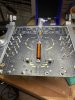

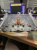

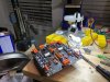
You might notice that somewhere along the way the output transistor sockets were installed... don't get me started on TO-3 sockets. Everything about these sockets was a huge p.i.t.a. from alignment, to the fact that they are ridiculously expensive. I followed the same strategy as the original boards in terms of hole placement and sizing, requiring that the tabs be carefully bent and that you use a metric ton of solder for each joint, even though I didn't need to. Determining the dimensions and hole spacing for these boards so that they could drop in without modification was a crucial step early in the design process, and with one exception (that didn't matter) I nailed it and therefore everything was aligned well enough so that I didn't really need to oversize the holes. In future iterations I will be sizing and placing the holes more appropriately for the component, especially after I ran into the only major issue encountered installing the sockets (which both fortunately, and frustratingly occurred on the last one being installed) when solder managed to flow down into the pin socket on the transistor sockets. Carefully removing the solder without damaging the socket was not something I want to do again. Honestly, I have been thinking about alternatives to the sockets altogether, perhaps something akin to the press fit studs and pin sockets used for the TO-66 sockets, we'll see.
Cornholio
New favorite google query "site:audiokarma.org"
Before moving on to the final assembly and testing, I wanted to show a solution I came up with for using TO-220 transistors in place of TO-66s in situations that rely on using the case of the TO-66 to connect to traces leading to other components, as is the case on the original boards. I had a few potential strategies worked out for this, including:
Let me know what you think, I am especially interested in spreading the good word on how to do this as it is a question/issue that I have seen many times across many forums across many years, and I myself have yet to find a another solution this (arguably) elegant and non-destructive/permanent.
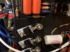
- Since I was designing the boards to be custom made, I considered simply connecting the pads of the TO-66 mounting holes with an extra trace, but a combination of wanting to stick to how it was originally done and personal preference lead me to not going this route, despite it being the obvious, easy solution.
- I have seen several solutions used by other folks involving soldering on a jumper, but decided that this was too messy and would affect the ability to quickly swap out silicon.
- I even briefly considered (I might still do this at some point) designing small adapter boards in the size and shape of a TO-66 transistor package that you can solder the TO-220 to and then treat the same as you would an ordinary TO-66.
Let me know what you think, I am especially interested in spreading the good word on how to do this as it is a question/issue that I have seen many times across many forums across many years, and I myself have yet to find a another solution this (arguably) elegant and non-destructive/permanent.

Wow, nice! What models are those jacks and binding posts if you don't
mind my asking?
Nice solution for the TO-220 s but I would have added the trace to the circuit board.
If I wanted to make TO-220 "bolt in" place of TO-66 s I'd probably cut 1/16" or even
1/8" copper into the footprint of a TO-66 and attach the TO-220 to it. I might even
fold up the sides to act as fins. But doubt that I'd ever do it due to the complexity.
mind my asking?
Nice solution for the TO-220 s but I would have added the trace to the circuit board.
If I wanted to make TO-220 "bolt in" place of TO-66 s I'd probably cut 1/16" or even
1/8" copper into the footprint of a TO-66 and attach the TO-220 to it. I might even
fold up the sides to act as fins. But doubt that I'd ever do it due to the complexity.
Last edited:
Cornholio
New favorite google query "site:audiokarma.org"
Wow, nice! What models are those jacks and binding posts if you don't
mind my asking?
Nice solution for the TO220 s but I would have added the trace to the circuit board.
Thanks, Pete!
The RCA jacks are Cardas CTFA (admittedly selected instead of the more expensive Cardas offerings because I wanted the color of the connectors to be consistent haha) and the binding posts Cardas CCGR-S
As for the TO-220s it was a tough choice, and adding the extra trace will likely happen in future iterations (actually I already have versions designed which include the extra trace), I think the final deciding factor was that I wanted to make the boards drop in replacements, and if I had added the extra traces well, to me at least, it would have felt like a bandaid that made it into production... by that I mean that the engineer in me really wanted to say "there will never be new TO-66s available, design it for the TO-220s" which would have resulted in tossing out the L-shaped heat sinks altogether (since they're primitive by today's standards), spacing out the transistors better, and using individual heat sinks for each TO-220, heck I could have even gone as far as to isolate the heat sinks from the rest of the board removing the need for the insulators, the shoulder washers, the studs, and achieving better cooling, but I digress. There's always next time!

I agree, eliminating the insulator would be an excellent improvement as there
is significant loss through the insulator. I'd probably try to make it look the same
as much as possible.
If you want to hear a funny story (not so funny for me), I was fixing an amp for a
friend with TO3 outputs. Some were dead, replaced them, nothing else seemed
bad, put one screw in to hold the TO3 s and just planned to see if it would bias up.
Everything seemed fine but it would not bias, or have low DC offset. After many
hours I put in the second screw and what do you know they used the case to
complete some of the connections. I thought, how could anyone make what I
viewed as such a mistake in the artwork. The chassis layout made it hard to see
the trace side of the board.
is significant loss through the insulator. I'd probably try to make it look the same
as much as possible.
If you want to hear a funny story (not so funny for me), I was fixing an amp for a
friend with TO3 outputs. Some were dead, replaced them, nothing else seemed
bad, put one screw in to hold the TO3 s and just planned to see if it would bias up.
Everything seemed fine but it would not bias, or have low DC offset. After many
hours I put in the second screw and what do you know they used the case to
complete some of the connections. I thought, how could anyone make what I
viewed as such a mistake in the artwork. The chassis layout made it hard to see
the trace side of the board.
Cornholio
New favorite google query "site:audiokarma.org"
Once all four driver boards were completely assembled, they were cleaned (for the 100th time) and closely inspected under a magnifier, followed by a few rounds of touchup/clean cycles. Once I was satisfied with the state of the boards (visual inspection passed!) I installed the L-shaped small heatsinks to the boards, as well as the smaller "TO-66" (actually TO-220) transistors. If you recall from my earlier posts about installing and soldering the press fit studs, this is the point where solder wicking up the studs became a slight issue. As I mentioned, in future builds of these boards I will be using a peel off temporary solder resist product applied to the threads, however fixing them as is was not a major issue and simply required some solder wick and turning up the iron a few notches--with the boards lying flat, face up, if I placed the solder wick at the end of each stud and timed removing heat just right I was able to only absorb the solder that caused issues with the threads.
Once I had the boards + heatsinks + transistors all together I went through some basic testing to check for short circuits (always always always check for shorts!), and it was a good thing that I did for doing so led me to discover a tiny design flaw (already corrected for V1.1!) in which R52/53 were mounted too close to the edge of the L-shaped heat sinks (not discovered in the design phase because I had been strictly measuring off of one set of the L-shaped heat sinks and the other set was a touch longer) which caused the case material of R52 on one of the boards to chip off, exposing metal and causing a short. Fortunately there was plenty of room available to adjust the resting place of R52/53 on the other boards to ensure clearance, and I always try and buy a few extras of each component so I was able to replace the damaged resistor.
Once I was satisfied and confident that there were no other shorts/issues I began the testing and final assembly portion of the build. In general I followed the test procedures in the original instructions, with a few caveats, including:


Once I was thoroughly convinced that the boards wouldn't summon any blue smoke genies, I moved on to the final assembly of the chimneys, installation of the output transistors, and installation of the wire harnesses I had made earlier in the process. You may notice the lack of heatsink grease and the blue pads-- these are dual purpose electrical insulator/thermal conductor pads that I decided to use instead of messy grease and film insulators. After researching these pads and using some engineer knowledge magic (aka reading the fine print, all of it) I deemed these to be a suitable alternative.

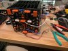
Although I don't have any photos of it, the next step was to do the initial tuning and bias adjustments under power, which I performed while the chimney assemblies were not yet installed in the chassis (I made a test harness to make this possible), and all four boards passed perfectly within spec.
Following the initial powered tests I installed the chimney in the chassis of each of the two units and performed the remaining powered tests and set the bias, all as instructed by the original build kit instructions, I was able to bias all four boards with ease and precision, and was pleased to see very close values across the boards.
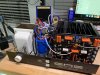
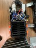
Here are both units just before I began the first listening tests. A few things that might raise some eyebrows here include:
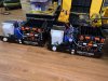
Below you will see my listening test setup, consisting of:

After a few hours of listening tests I decided for fun to install the top cover on the unit without the meters and threw the end caps from the metered unit (the older unit was bought sans end caps, will be making new ones soon though) just to see what the whole package fully assembled will look like... pretty snazzy if I do say so myself.

Here's another one with the one unit sitting atop the fully assembled unit (with all of this moving the units around I am thinking about cancelling my gym membership, what a workout!)

Since this post has already grown quite long I am going to leave it at that for now, but stay tuned for soon-to-arrive posts discussing the following, among other things:
Once I had the boards + heatsinks + transistors all together I went through some basic testing to check for short circuits (always always always check for shorts!), and it was a good thing that I did for doing so led me to discover a tiny design flaw (already corrected for V1.1!) in which R52/53 were mounted too close to the edge of the L-shaped heat sinks (not discovered in the design phase because I had been strictly measuring off of one set of the L-shaped heat sinks and the other set was a touch longer) which caused the case material of R52 on one of the boards to chip off, exposing metal and causing a short. Fortunately there was plenty of room available to adjust the resting place of R52/53 on the other boards to ensure clearance, and I always try and buy a few extras of each component so I was able to replace the damaged resistor.
Once I was satisfied and confident that there were no other shorts/issues I began the testing and final assembly portion of the build. In general I followed the test procedures in the original instructions, with a few caveats, including:
- I have several versions of the assembly instructions on hand, and each gave different values for the resistance tests, and the readings I was getting didn't match any of them, some by a little, some by a lot. Although this made me a little nervous, through deductive reasoning I determined that it would be safe to proceed, especially considering that the readings of the four boards I had built were quite consistent with each other (one benefit of building the driver boards four at a time is you can more-easily identify big issues by comparing the readings of one board to the other three, I was lucky, I didn't discover any anomalies) and the readings compared to those in the original instructions were roughly proportional related to each other.
- Jumper placement was different, due to the fact that my boards are one piece, but translating to the new boards was simple, as the jumper setup presented in the original instructions for the original boards was equivalent to placing a jumper between the emitter and base pins of the four output transistor sockets, along with a jumper across both pins of C24.
Once I was thoroughly convinced that the boards wouldn't summon any blue smoke genies, I moved on to the final assembly of the chimneys, installation of the output transistors, and installation of the wire harnesses I had made earlier in the process. You may notice the lack of heatsink grease and the blue pads-- these are dual purpose electrical insulator/thermal conductor pads that I decided to use instead of messy grease and film insulators. After researching these pads and using some engineer knowledge magic (aka reading the fine print, all of it) I deemed these to be a suitable alternative.
Although I don't have any photos of it, the next step was to do the initial tuning and bias adjustments under power, which I performed while the chimney assemblies were not yet installed in the chassis (I made a test harness to make this possible), and all four boards passed perfectly within spec.
Following the initial powered tests I installed the chimney in the chassis of each of the two units and performed the remaining powered tests and set the bias, all as instructed by the original build kit instructions, I was able to bias all four boards with ease and precision, and was pleased to see very close values across the boards.
Here are both units just before I began the first listening tests. A few things that might raise some eyebrows here include:
- Mounted to the side of the chimney just about the filter caps, facing the transformer, are MOSFET protection boards that I bought from Tom at Neurochrome (no affiliation, but these things are pretty sweet, and Tom's customer service is, well, simply put: incredible. I had some back and forth with him prior to purchasing regarding the modification to the parts list needed to run the boards at the higher power of the Ampzillas and he was beyond helpful, and responded so... fast really doesn't do it justice, more like light speed... to every question with thorough explanations)
- Just in front of the transformer/filter caps there's a black box with a dial on it--this is a fan speed controller, and is very much so temporary, but more on that later once I get to talking about what's left to do, troubleshooting, and final touches.
Below you will see my listening test setup, consisting of:
- My Bryston 1B preamp, which is admittedly midway through a bit of restoration work itself (I didn't previously have an amp to test it with or a proper testing setup, however after using it over the past few days I am starting to think that a bit of a re-capping and cleaning of controls is due, it is, after all, over 40 years old now! (note that I have also installed an IEC no-mod power box already, and not visible is that I have replaced all of the IO RCA jacks with new, gold plated jacks which were particularly hard to get my hands on, but necessary as the originals were in really rough shape)
- The preamp is sitting on top of a basic Furman sequencer/power conditioner, really only using it for the sequencing part for now, and even that isn't ideal (on my to do list is figuring out if I can adjust the delay)
- My good old Technics SLQ350, which I now believe to be the weakest link in the system (all initial listening tests were vinyl)
- A pair of Advent "OLA"s that I originally bought to butcher for the woofers, but have since developed a fondness for, as they sound great (to my untrained ear, and definitely better than what I was doing before) and are in beautiful condition.
- Two pairs of custom made Canare/Neutrik interconnects that I threw together quickly for testing
- A set of cat 5e speaker cables that I quickly threw together for testing, I didn't want to tap into my supply of bulk cable I have for the final cables yet, and I am too embarrassed to say what I had been using before
- A variac, call me paranoid, but I needed to do some significant supervised testing before I was willing to start up the amps 0 ==> 100 power wise, it has since been yanked from the test setup
After a few hours of listening tests I decided for fun to install the top cover on the unit without the meters and threw the end caps from the metered unit (the older unit was bought sans end caps, will be making new ones soon though) just to see what the whole package fully assembled will look like... pretty snazzy if I do say so myself.
Here's another one with the one unit sitting atop the fully assembled unit (with all of this moving the units around I am thinking about cancelling my gym membership, what a workout!)
Since this post has already grown quite long I am going to leave it at that for now, but stay tuned for soon-to-arrive posts discussing the following, among other things:
- cooling fan issues
- the protection boards in detail
- component selection
- board design
- issues/lessons learned
- hard to find parts (those power switches still haunt my dreams)
- how I will factor these into my budding system
- meters for the unit that has them (small sub project)
- future related work, including the possibility of reproducing other versions, as well as making near-exact replicas of the original boards
- the possibility of putting together a "new" Ampzilla kit for others who want to roll their own
- power transformers
Last edited:

I think the Dynaco ST-400 and ST-416 used the same power switch, imagine that both amps designed by JB. Anyway it's another way to search for them, someone's always parting out Dynacos on that auction site. The later Ampzillas used Leviton wall switches, still available in rocker style from Lowe's or Home Depot in several colors.
Craig
Craig
Cornholio
New favorite google query "site:audiokarma.org"
I think the Dynaco ST-400 and ST-416 used the same power switch, imagine that both amps designed by JB. Anyway it's another way to search for them, someone's always parting out Dynacos on that auction site. The later Ampzillas used Leviton wall switches, still available in rocker style from Lowe's or Home Depot in several colors.
Craig
As far as I can tell, the original switches for the Ampzilla I were repurposed "appliance" switches, the type used for dryers and electric ovens/cooktops.
My requirements for finding replacements were that they are new/unused, meet/exceed specifications, that I could get two of (originally I wanted to find something readily available today, still do in fact, however most readily available options were just too plain expensive, as a compromise I bought several extras of the ones I found and might buy out the rest from the seller), and that were manufactured by a reputable company. I also wanted to stick to the originally specified DPDT type, even though it's not really necessary, with that said, I am going to be converting the fans to 12vdc and will actually be utilizing both poles for that and wiring for [fan only - off - fan + amp] as was done with the originals. I will continue to search for current production switches that will work, however it's not a particularly easy thing to find for a reasonable price--certainly there are many options out there at reasonable prices that would work, the problem is ensuring that they meet electrical specifications, since the newly made ones are typically sold for specific appliances and almost never state electrical ratings.
Cornholio
New favorite google query "site:audiokarma.org"
So throughout my listening tests so far I have been keeping a list of issues that arise, or additional things that need fixing. I'll start with the cooling fans.
First things first, the old fans had to go, they were both loud and dirty to the point where cleaning would be impractical or even destructive, and worst of all (in my mind, at least) they were different from each other (same make/model, different levels of noise) so I decided to replace the original boxer fans.
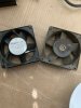
Although I did briefly consider retrofitting to use a DC cooling fan, I wanted to give AC fans a chance still, and so my first attempt at replacing with quieter fans was using AC powered fans powered by the secondary coil of the transformer.
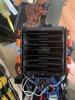
Prior to purchasing the replacements shown installed above, I did a ton of research into the quietest AC fans available, and let me just say... what a mess that world is. It would seem that manufacturers are free to list whatever noise level they decide in fan specifications, and they almost never state how the fan was hooked up/powered in order to achieve those noise levels, so the search involved a lot of cross referencing to make the determination as to which fans to buy, and even after all of that I still bought the wrong fans the first time around (currently installed). Not to say there's anything wrong with them per se, they fit and function, they just happen to be too loud, too fast, and push too much air. Directly connected to the transformer output these were completely unacceptable, so the photos in posts above feature speed controllers set to the slowest setting. Even at the slowest setting the fans were still too loud to be acceptable, not to mention they emit a buzzing sound below a certain speed. I will note that I did also try several combinations of inline resistors, all of which failed to get everything to an acceptable level of performance. After several hours of additional research I arrived at the conclusion that it would be either highly unlikely, or prohibitively expensive, for me to find an acceptable (read: silent) solution that involved an AC fan and decided that the best route to go would be to retrofit the units such that I could use ultra-quiet 12VDC computer fans. This made the search considerably easier as I already knew where I would find the answer: Noctua. (when in doubt, just go for Noctua, in my opinion, high quality engineering and manufacturing, good reliability)

I went ahead and acquired two of their absolute quietest fans, which also happen to be two of their least expensive 120mm fan offerings. These super powered bad boys top out at a blistering 700 rpm, even slower with the noise reduction resistors I bought to accompany them, and while they don't move a huge amount of air and aren't ideal for high impedance situations (e.g. intricate heat sinks) they should be absolutely perfect for the Ampzilla. In testing them out, they're incredibly quiet, but I won't know exactly how quiet until I decide how to power them, as my bench PS is considerably louder (although brief tests with an old 12vdc adapter have shown that they are effectively silent running).
So great, I have nearly silent fans, but that still leaves me with the problem of powering them... before the suggestions come in, here are a few commonly discussed options I have ruled out:
With that said, as I mentioned, I do not have expertise in this area, so there are possibly factors that I have not yet considered, and I am interested in learning what the community has to say about this, so please share your thoughts if you have them!
First things first, the old fans had to go, they were both loud and dirty to the point where cleaning would be impractical or even destructive, and worst of all (in my mind, at least) they were different from each other (same make/model, different levels of noise) so I decided to replace the original boxer fans.
Although I did briefly consider retrofitting to use a DC cooling fan, I wanted to give AC fans a chance still, and so my first attempt at replacing with quieter fans was using AC powered fans powered by the secondary coil of the transformer.
Prior to purchasing the replacements shown installed above, I did a ton of research into the quietest AC fans available, and let me just say... what a mess that world is. It would seem that manufacturers are free to list whatever noise level they decide in fan specifications, and they almost never state how the fan was hooked up/powered in order to achieve those noise levels, so the search involved a lot of cross referencing to make the determination as to which fans to buy, and even after all of that I still bought the wrong fans the first time around (currently installed). Not to say there's anything wrong with them per se, they fit and function, they just happen to be too loud, too fast, and push too much air. Directly connected to the transformer output these were completely unacceptable, so the photos in posts above feature speed controllers set to the slowest setting. Even at the slowest setting the fans were still too loud to be acceptable, not to mention they emit a buzzing sound below a certain speed. I will note that I did also try several combinations of inline resistors, all of which failed to get everything to an acceptable level of performance. After several hours of additional research I arrived at the conclusion that it would be either highly unlikely, or prohibitively expensive, for me to find an acceptable (read: silent) solution that involved an AC fan and decided that the best route to go would be to retrofit the units such that I could use ultra-quiet 12VDC computer fans. This made the search considerably easier as I already knew where I would find the answer: Noctua. (when in doubt, just go for Noctua, in my opinion, high quality engineering and manufacturing, good reliability)
I went ahead and acquired two of their absolute quietest fans, which also happen to be two of their least expensive 120mm fan offerings. These super powered bad boys top out at a blistering 700 rpm, even slower with the noise reduction resistors I bought to accompany them, and while they don't move a huge amount of air and aren't ideal for high impedance situations (e.g. intricate heat sinks) they should be absolutely perfect for the Ampzilla. In testing them out, they're incredibly quiet, but I won't know exactly how quiet until I decide how to power them, as my bench PS is considerably louder (although brief tests with an old 12vdc adapter have shown that they are effectively silent running).
So great, I have nearly silent fans, but that still leaves me with the problem of powering them... before the suggestions come in, here are a few commonly discussed options I have ruled out:
- use a wall wart and power the fan externally (no no no no no, not in a million years, I will never do that... that "poster child for cutting corners", IMO it's lazy beyond belief and is just asking for trouble in the form of forgetting to plug in the fan, if you couldn't tell, I feel strongly about this)
- same as above, but hard wiring the wall wart inside the chassis (yes? no no no no no, among many other reasons, including wrong tool for the job, I need two identical PSs, one for each unit, meaning that these wouldn't be coming out of my large box of orphaned wall warts, meaning I will be buying new whatever solution I arrive at, meaning that if I am spending money on new parts I am at least going to buy the correct parts for the job)
- tapping the driver boards (just no, while this would likely work, and probably wouldn't noticeably affect anything, quite simply it is not a good practice)
- going the "purist" route and adding a mains --> 12vdc linear power supply (while I would jump at this option otherwise, as it is likely one of the best routes to go, what can I say, it's hard to justify the exorbitant cost of new linear PSUs, and that's coming from a guy who spent ~$300 on connectors, the ROI is simply too low)
- DC-DC converter powered at the positive filter cap
- cost is still somewhat of an issue, as is packaging/size of converters, possibly limiting options based on what I can squeeze in the chassis
- small, low power, correctly spec'd switching mains-->12vdc power supply (leaning in this direction)
- They're tiny, specified for just this sort of an application, and quite inexpensive
With that said, as I mentioned, I do not have expertise in this area, so there are possibly factors that I have not yet considered, and I am interested in learning what the community has to say about this, so please share your thoughts if you have them!