• The move to the new server is done. There are some software and database maintenance updates in process. This has us passing the hat around to help out. We appreciate any donations. Seriously, even a dollar helps. The payment page may be found here - https://www.audiokarma.org/support.html

the good, the bad, and the ugly (part II) (Yet another Ampzilla restoration thread)

Nice work, very nice!

Do you have any comments on the design overall? It uses a series output stage because
there were no high voltage output devices back then, also the SOA is better. I studied this
design as a kid when I was trying to decide between building it or the Tigersaurus amps.
I chose the Tigersaurus as it seemed a bit cleaner to me and built it from scratch including
etching the PC board.

It seems to me that your boards and other work would go nicely at the updatemydynaco
website:
https://www.updatemydynaco.com/
or the site that offers the full Adcom GFA555 rebuilds:
https://hoppesbrain.com/adcom-service-and-refurbishing/
 
Last edited:
The later versions, II and IIa, used plug-in edge connectors but sadly those connectors are NLA. If not using plug-in connectors the top to bottom board connection needs to be flexible so as to be able to service the top board without having to remove the bottom board. Then again you don't want to rely on the traces as the sole mechanical connection either. What to do?

Craig

Although the exact edge connectors may be unavailable, I would be happy to help you spec out some modern equivalents, especially if you happen to still have the schematic for the meter board! (I have noticed you are a respected authority on GAS/SAE not just here at AK!)

As for those TO-66s, I've nearly located replacement originals for all of mine, but I will also be ordering the TO-220 equivalents because why not, they're so cheap, and I am on the same boat thinking about having to connect the collector pins... I mean, it's easy enough for me to bridge the two on the top layer when re-making the boards, however there really ought to be a better way. I have done some researching to see if I could find anything but sadly those TO-66-packaged transistors seem to be a dying breed.

That said, one idea that I have had so far would be to design up some small boards with the same footprint as the TO-66 and same connections, and either have a smaller, but modern and likely better dissipating, heatsink mounted to it, or paying a bit extra to have them made from thermally conductive PCB material. Either way, with the option of solder-on or socket for the TO-220s. (leaning towards the sockets, who doesn't want the ability to quickly swap out transistors for comparison?)
 
Nice work, very nice!

Do you have any comments on the design overall? It uses a series output stage because
there were no high voltage output devices back then, also the SOA is better. I studied this
design as a kid when I was trying to decide between building it or the Tigersaurus amps.
I chose the Tigersaurus as it seemed a bit cleaner to me and built it from scratch including
etching the PC board.

It seems to me that your boards and other work would go nicely at the updatemydynaco
website:
https://www.updatemydynaco.com/
or the site that offers the full Adcom GFA555 rebuilds:
https://hoppesbrain.com/adcom-service-and-refurbishing/

Not too many comments yet, as it's the first amp design that I have studied in-depth, though I am sure that as soon as I add another to my repertoire (like, say, the "in need of repair" Bryston 3B that arrived yesterday) I will have many comments on the design of the boards. As for the overall design of the Ampzilla, as an engineer I think that it is absolutely beautiful in its simplicity, with the only caveat being that perhaps they could have used a mech-e when it came to the heatsink, as the same amount of metal could have easily been used in a way that would have allowed for better cooling, though with that said, I have read many a story where claims are made that it sounds better running a bit hot, so maybe it was intentional.
 
I don't know if you are familiar with the "Tiger" amps from PE in the 1960s - 70s but
they had a reputation for going up in smoke - big time. What was shocking to many
of us is that the 3B borrowed much of the Tigersaurus design with even more current
gain in the output stage.
I've simulated many of these designs at DiyAudio, I'm PB2 there:
Post #12 has the Tigersaurus schematic in case you want to take a look, I provide LTSPICE
simulation files there also:
https://www.diyaudio.com/forums/solid-state/189970-swtpc-tigersaurus-250w-amp-simulation-2.html

Bryston 3B LTSPICE simulation:
https://www.diyaudio.com/forums/solid-state/301321-bryston-3biii-spice-simulation.html

Old thread where I find the reverse Vbe problem in the Tiger amps:
https://www.diyaudio.com/forums/solid-state/93637-swtpc-universal-tiger-improved-simulation.html

SWTPC Tiger madness:
https://www.diyaudio.com/forums/solid-state/344509-tiger-amp-madness.html
 
As for those TO-66s, I've nearly located replacement originals for all of mine, but I will also be ordering the TO-220 equivalents because why not, they're so cheap, and I am on the same boat thinking about having to connect the collector pins...

While this is not a great pic, here is what I did when I replaced the TO-66s with TO-220 in a Marantz 250. I had to tie both the collector pins.

Let me know if you need additional pics.
 
I don't know if you are familiar with the "Tiger" amps from PE in the 1960s - 70s but
they had a reputation for going up in smoke - big time. What was shocking to many
of us is that the 3B borrowed much of the Tigersaurus design with even more current
gain in the output stage.
I've simulated many of these designs at DiyAudio, I'm PB2 there:
Post #12 has the Tigersaurus schematic in case you want to take a look, I provide LTSPICE
simulation files there also:
https://www.diyaudio.com/forums/solid-state/189970-swtpc-tigersaurus-250w-amp-simulation-2.html

Bryston 3B LTSPICE simulation:
https://www.diyaudio.com/forums/solid-state/301321-bryston-3biii-spice-simulation.html

Old thread where I find the reverse Vbe problem in the Tiger amps:
https://www.diyaudio.com/forums/solid-state/93637-swtpc-universal-tiger-improved-simulation.html

SWTPC Tiger madness:
https://www.diyaudio.com/forums/solid-state/344509-tiger-amp-madness.html

Seems like some interesting stuff, I will definitely check it all out once I get deep enough into this all to start simulating circuits!
 
While this is not a great pic, here is what I did when I replaced the TO-66s with TO-220 in a Marantz 250. I had to tie both the collector pins.

Let me know if you need additional pics.

The more I think about it, the more I think that this world would be a better place if someone were to whip up and have made some TO-66 to TO-220 conversion boards that don't require jumpers. No promises yet, but I might just do so myself. If I do I will definitely reach out to the community here to see if anyone else would be interested in such a thing (especially since the per-piece price of getting them made goes down fast with quantity).

On that same note, as I continue work on the replacement board design I am considering the possibility of one or more of the following:
a) "baking it in" such that the boards will feature the collector pads already tied together
b) also including pads/holes for the use of TO-220 footprint transistors
c) either using sockets (they can be a bit tough to find for TO-66s though) or board mounted pin sockets (there's probably a better word for those, all I know is that they do exist!) to make it such that the TO-66s can be swapped out as easily as the big TO-3s can

Joe
 
The meter board schematic is part of the chassis schematic, where do you want it sent?

Craig

PM'd on the schematic, now on to those edge connectors, I am currently performing a search for a compatible replacement, fortunately I have those new, never used IIa boards to get the dimensions for the socket side, unfortunately I don't have the output boards, but from what I can tell from the photos I have found the real challenge will be finding a fit for the main board side, in the meantime, you wouldn't happen to have any close up photos of where the pins on the output boards are attached to the PCB, would you?
 
It sure has been too long since I posted an update, especially considering I spend nearly all of my non-working awake time working on this...

So as I have shown before, I have built up several versions of the Ampzilla boards in Eagle cad, but I have thus far been a bit hesitant to jump to ordering them from a board house, and one of the reasons for that has been that when it comes to the mechanical side of things (holes, solder pads, positioning, etc) Eagle really su... has a lot to be desired. Although most of what I have done so far has been either replicating the original boards I have on hand, the tolerances used when producing these boards were pretty rough by today's standards, and anyways, I could ramble on about the why's and the wherefores but instead I'll jump to the conclusion: I have been working on two things in particular:

1) a single-board replacement board which will probably be the first one I have printed

2) reverse engineering the overall Ampzilla (sounds fancier than it is, a six year old with a ruler and poor eyesight could do it) and building it in CAD

Well, to keep it short as I can't seem to find my words today, the two are starting to look a lot more like one... and... anyway, here are some renderings that I would like to discuss with everyone a bit:

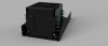
Starting with a more assembled look, we have:

Ampzilla v16 angle.png Ampzilla v16 front.png Ampzilla v16 side.png Ampzilla v16 top.png

Which is all terribly boring, and to be honest I really wanted to write this post for these renderings:

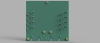
pcb v30 back.png pcb v30.png pcb v30 angle.png

These sparsely populated boards represent some of the trickier parts of what I have been working on (trickier mostly because this was primarily an exercise in parts sourcing, which is definitely a strong suit of mine, however sourcing in a way that doesn't cost an arm and a leg can get complicated quickly and is often time consuming) the past few weeks. As there will already be some significant changes to the overall board design (but not the schematic, and only minimal trace changes) I decided to take the liberty of fixing a few places where the Zilla's more prehistoric side was beginning to show through. These were done up in regular CAD mostly due to the fact that they're all mechanical parts, but anyway here's a rundown of what the changes are, and I am interested in any feedback anyone might have:
  • Lets start with those pesky TO-66 transistors:
    • I am really, really, really, not a fan of those soldered-on nickel plated screws, and while I certainly wasn't around in the early/mid 70s I can't imagine that there wasn't a better way to do this back then, but then again... never mind, I'll keep my politics to myself! Anyway, I also didn't want to get too fancy/modern (also mad this a lot slower of a process trying to adhere to that), I wanted something made of modern materials, but was still pretty raw and unsophisticated, and, of course, simple. What you see there in those renderings are PCB studs, and they happen to be made by the same company that made the clinch nuts (it's okay to laugh a little, times are tough) that give threaded 6-32 (I am begrudgingly sticking with imperial units, often just using the metric conversion, and I haven't used these units for anything digital since the first semester of college because I had to for an assignment), which I would argue especially keeps in within the same style, right? It does also raise the question of why didn't they do this for the Zilla, but I digress. In the exact same way those clinch nuts bind themselves to all that aluminum with a short length relative to the panel thickness of knurled stud slightly larger than the diameter of the hole. If the holes are plated then there's your first area of contact, but they're also tinned and designed to be soldered to, so you press it in the board and seal everything tight with solder and there you go. This leads to the next change...
    • You might be wondering, "sure the screws are a p.i.t.a. but you do it once and you're done and you don't have to mess with it again", but I am not designing this as a production style board, it's a prototype, one that I fully intend to mess with it, hence my extra effort on a more-solid approach to the mount screws/collectors. But you may also be thinking "Well, you're still going to have to take everything apart to desolder the transistors" which leads me to the next change, admittedly a bit more on the modern side, but it isn't terribly apparent by looking at them, but anyway what I am referring to are the through-board pin socket connectors. These tiny, machined contraptions come in several varieties, among them are many that bind themselves to the board using the same mechanism as the studs did, however I am opting for the solder in variety. Inside each socket is a tiny, fancy multi-fingered spring contact that ensures good contact, vibration resistance, etc. Essentially what I did was built a TO-66 socket into the board. Honestly I should probably just do the TO-3s using the same type of sockets... but more on that later.
    • As a side note, I have been occasionally working on a design for an inexpensive converter mount to allow for the use of TO-220 variety transistors in place of TO-66s without requiring any further modification to the board. More on this to come.
  • I should probably mention the board itself:
    • One piece
    • You'll notice that the area where the smaller board would have been has been extended to the same width as the main board, more on that below.
    • The renderings don't show it, but it's going to be a 2 layer, because why not, and I can eliminate the jumpers, though I don't plan on significantly changing the board wiring. (Though I have been toying with the idea of attempting to pull off a perfectly, well, with very few exceptions at least, symmetric wiring design)
  • Next lets discuss turrets:
    • I'm not a huge fan of these either, however as I have learned more about turrets (yeah, I guess I really am that boring, aren't I) I have a newfound appreciation for them, can totally see why they were used, because they're ubiquitous in the guitar amp world, and are still used today, but there's just something unsettling to me about having those bare power turrets with everything jammed in here... (note that my boards come with really great "forensic data" regarding which parts were perhaps spec'd a little lighter than they should have been... but more than you will ever care to hear about components is coming soon, so I'll spare you of most of that for now) (also, I guess I found my words after all) where was I... oh yes, turrets, I don't want to do turrets anymore, but that left me with the challenge of deciding what to do instead...
  • Power/signal to/from the board:
    • Wanted something beefy
    • Don't want it to be soldered
    • I don't know why, but I am not a fan of quick disconnects, well, not for this I'm not, I have parts cases full of them and special crimp dies, I am a fan of them, I just didn't want to use them here, they didn't feel right.
    • I also didn't want screw terminals, even if I were to use ferrules (I am so interesting that I have a collection of these, along with tooling, as well), though I think it would be raw enough.
    • They're not the right color in the renderings but what you see there are screw terminals, with small studs on them, so that I can use ring terminals and locking fasteners for a tight connection that I can have confidence in, and oops, they only come in metric sizes.
    • This leads to the output signals from the boards, which, in addition to being moved to the center of where the gap would be, are the same type of connector, chosen for the same reason.
    • With that said, I am not married to these ideas in particular.
    • Next are those old ceramic caps tying the boards to the chassis. I just plain don't like component hanging off the board like that. Since I expanded the board section representing the output board, I am opting for the minor change of locating those caps on the board now, and, as you might have noticed in the rendering, using standoffs to tie the boards to the chassis.
    • That leaves us with getting the signal to the board, definitely axing the turrets there too, and opting for a connector. Well, since it already calls for a shielded cable... and this one came to me with a thin coaxial cable installed, I started thinking along the lines of RF connectors. First I was thinking BNC because ideally I want something that locks, however even BNC mini was still too large of a form factor to fit, what I ended up going with, for now at least, is SMB connectors due to the combination of size, availability, they snap on (would prefer locking, but this will suffice), and can be had for a reasonably low price. That, and they're also designed with shielding in mind (the original design calling for shielding leads me to think that using unshielded wire in such close proximity to everything else might lead to some issues)
  • So there are probably other things that I am forgetting right now, but I do want to mention one last grievance with the world: quality TO-3 sockets are outrageously expensive. First, not too many component/connector manufacturers make them anymore. Next, the surplus market for them is pretty bleak. This sort of leaves you forced to buy new. Now I could simply toss the old ones into an ultrasonic bath to clean them, but perhaps the single greatest reason why it might seem like I am making rather slow progress is because I have for a while now decided that if I am going to do all of this extra work of modeling, replicating boards, building out BOMs, that it's going to be for a better purpose than just wasting more time to get through the plague, at the end of this I want to have amassed in a single place all of the information, designs, links, parts, components, and so forth that one would need in order to construct a completely new 'Zilla should they be so inclined. Reeling myself back in, and getting to how all of that relates to TO-3 sockets, is that I intend to replace them anyway, in part to demonstrate that I can find every part needed to build one from scratch, affordably (well, for someone else, my boards are going to embarrassingly bejeweled ha ha a certain Canadian part seller already has a bunch of my money to prove it), and easily, without having to wait for some rare bit to pop up on the bay. But also returning to those darn sockets, even going the cheapest route, which I probably will for these at least, unless I try a non-socket alternative, by using the keystone ones (nothing against the brand, it's just the budget brand, still quality) that's about a $30usd investment minimum, take it up a notch to the TE budget variety and that brings you to $13usd a pop. And don't get me started on companies like TE... who are massive monolithic... can I make a Trek reference here? Okay for those of you possibly Trek people, TE is the Borg. (the rest of you just google it)
But anyway... that's all for the night!
 
Quick update: my restoration queue just got a bit longer... (pictured on the left)

IMG_1135.jpg
 
Updates!

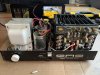
Yesterday I did a rough teardown of the newer (and new to me) Ampzilla. Here's what I know so far:
  • I knew this before purchasing, but this one is another candidate for a full rebuild, in spite of its overall good condition, at least in appearance
  • As I had suspected prior to purchase based on the style of Ampzilla badge on the front, it is an Ampzilla I
  • Based on the build quality I think that it can be safely assumed to have been purchased originally fully assembled
  • Unfortunately, as was the case with the first 'Zilla, the serial number sticker is missing
  • It is a later variant of the Ampzilla I than my first 'Zilla, the main boards are marked "GAS 790001" and the lower boards are labeled "GAS 90003".
  • As for the chassis, the only differences I notice right off the bat are:
    • the rear pair of holes for mounting the transformer have been replaced by slots
    • It only has one set of outputs, the binding posts. The older one I have has two sets: binding posts and quarter inch phono, though I suspect that the phono style outputs might have been a custom addition done by the original owner
    • The hole next to the inputs is smaller and occupied by a screw, the older one had a larger hole that was occupied by a spst switch, again, I suspect that this was a modification by the original owner. The switch was wired such that it simply selected which channel input to use, with the rest being wired up to run in mono. Also this newer one has RCA inputs, the older one used quarter inch phono input connectors.
  • I suspect that my disassembly was the first time that the unit had been opened up since it was new, I base this off of finding things such as a few stray drops of solder.
Here are my current thoughts/plan:
  • I am definitely going to strip down the boards, documenting the components and will do the same reverse engineering/cad modeling type work as I have done with the previous version
  • I am absolutely going to rebuild this one as well
And now I have some questions that I am hoping some of you may be able to help me answer:
  • By appearance and board markings, can anyone help identify where along the line of revisions this particular unit belongs?
    • It's definitely a later unit for a Ampzilla I, the "79" on the main board makes me think that those are a revision that was done in 1979, but I don't know what nomenclature was used in the numbering. That said, I believe this to be of a more-common variant, as a majority of the examples of the Ampzilla I I have found appear to have the same boards.
  • Can anyone tell me anything about the differences between my earlier version and this revised version?
    • Is the newer one known for being "better" in any way? (revised doesn't always mean better!)
    • Any audible differences in how they might sound?
    • This sort of throws a wrench in some of the work I have been doing in making replacement boards so far, not a huge amount of work, but if I am going to rebuild a second one and use both in my setup (haven't decided how yet, as I do have that Bryston as well, I was thinking perhaps now that I have two 'Zillas and the bryston 3B, that maybe I'll stick with the original plan for the Bryston to drive the two passive subs I am also working on, and then either: a) bi-amplify the DQ-10s such that one zilla does the high frequencies for both speakers and the other does the lower frequencies for both, with the idea that if the two 'Zillas aren't rebuilt in an identical way that it won't present itself as one speaker sounding different than the other or B) rebuild both 'Zillas identically, with the same replacement boards, components, etc (my wallet is getting nervous haha) and run each in mono) then I will likely decide to use the same components on both rebuilds.
    • Although it is possible and probably likely that the cause of failure was different for both 'Zillas, unlike the older one these boards don't immediately identify any components that were perhaps a bit underrated e.g. no obvious heat damage.
  • On the newer boards, along with many example photos of similar boards I have found, there are several components that appear to have been initially included in building the boards, but then removed, leaving only the empty space with the component outline and tiny stubs of the leads sticking out of the boards, some of these are: L1, L2, C16, C18, R48, and so on. Can anyone tell me why that is?
    • Were they just used for calibration during assembly and removed as unnecessary after final checkout?
    • Was there a revision made after the boards were printed (seems unlikely as it would appear that the components were at one point installed, but then again I have no idea what was originally soldered in leaving the stubs)?

IMG_1139.jpg IMG_1140.jpg IMG_1142.jpg
 
Your "new" boards are the same ones I have, 790001 and 3. Changes from the earlier boards were supposedly only mechanical in nature. There's a post by an ex-GAS tech somewhere about the removed parts, all in the limiter circuit. This was done by the techs at the factory., the reason is unknown, they were just told to do it.There are two assy. manuals for this version on the interwebs so you can download what you actually have this time. You will see there's no electronic differences. I will send them to you.

I've decided what I'm going to do about my turrets. For the inter-board connections I'm going to replace the turrets with eyelets and use simple wire jumpers as large of a wire that will fit into the eyelets. There's really only a couple of wires carrying any amount of current. For the power supply connections I will replace the output xsistors sockets with ones that have a long collector tab and connect the PS wires directly to them. For the inputs and outputs I will use eyelets and solder the wires in the eyelets.

Craig
 
Your "new" boards are the same ones I have, 790001 and 3. Changes from the earlier boards were supposedly only mechanical in nature. There's a post by an ex-GAS tech somewhere about the removed parts, all in the limiter circuit. This was done by the techs at the factory., the reason is unknown, they were just told to do it.There are two assy. manuals for this version on the interwebs so you can download what you actually have this time. You will see there's no electronic differences. I will send them to you.

I've decided what I'm going to do about my turrets. For the inter-board connections I'm going to replace the turrets with eyelets and use simple wire jumpers as large of a wire that will fit into the eyelets. There's really only a couple of wires carrying any amount of current. For the power supply connections I will replace the output xsistors sockets with ones that have a long collector tab and connect the PS wires directly to them. For the inputs and outputs I will use eyelets and solder the wires in the eyelets.

Craig

First things first, thank you so much for sending me those docs Craig! They have been super helpful!

So I am just starting to really dive into things as I finished stripping and cleaning the 790001/790003 boards at the end of last week. So far it would seem that most of the changes are in fact mechanical (including power ratings as a mechanical change like a "good mech-e"), save for a few that I still need to do a full schematic comparison to verify whether they were changed or whether I breathed a little too much of the fumes from all that desoldering!

With that said, I am still curious and will have to search a little harder to see what else I might be able to dig up on those removed parts--as that certainly changes the circuit electronically (not the actual amplifier circuit though, from what I can tell)--it just seems like an awfully drastic change to the boards overall. I also would note that in my search for photos I have come across photos of both stock and restored boards, both with and without the parts removed, so, well, I guess the only result of that is that my curiosity is further piqued!

As for your solution, that'll definitely do! Though good luck finding those sockets for a reasonable price, and definitely save the ones you pull, it would seem that TO-3 sockets are going the way of landlines!
 
Hey Craig @llwhtt and anyone else who might know,

Any idea what the deal is with the resistor-capacitor in series that is tying turrets B and L (from the schematic at) that my unit came equipped with and is seen below?

Screen Shot 2020-09-02 at 8.29.19 PM.png
 
Just got a new pair of blank Ampzilla IIa boards, another project that I really don't need at the moment but couldn't help myself.
 
Just got a new pair of blank Ampzilla IIa boards, another project that I really don't need at the moment but couldn't help myself.
I know how you feel, I hope you spotted those connectors for the main-output boards he's got too!

For the rest of you, I am still actively working on this, I swear it hasn't died yet, it's just been a hectic proposal season for me at work the past month or so!
 
Updates updates updates!

I apologize for the frequent periods of radio silence, the project has continued non-stop, however life is life and I don't always have quite as much free time as I would like...

With that said, on to the fun stuff, though sadly no photos today. My updates for today center around two things: new boards and new end caps for the chassis

I'll start with the end caps, since there's not a whole lot to say. As you all may recall, my first of the two units I am currently rebuilding arrived sans the white metal end caps. As I prep to have the new PCBs made and do the final parts orders, I nearly forgot that this is an issue that I haven't yet settled on a solution for, or even really looked into yet, until today. As the second 'Zilla did arrive with the white end caps, I was able to whip up the simple design in CAD, and I am now in the process of seeking a shop to make some new ones, which is where all of you come in! Since I know at least one reader of this thread is in need of some new end caps (cough, Craig! @llwhtt), and figure there may be others, and due to the fact that the price per piece becomes significantly cheaper to have made as quantity goes up, I would like to open this order up to the fine folks of AK! As I wish not to anger any of the very fine moderators, I will abstain from talk here that best belongs in another forum, however I will say that with just a little searching, should my order get up to at least 10 (so 5 sets of 2) then the piece price for bare metal shipped would be roughly 35 a pop (times 2 for a set brings it to around 70 a set), and would only go down from there. I am also looking into options for getting them painted or powder coated as well, in addition to me finally breaking out that HVLP paint rig I dropped a small fortune on earlier this year. If you're interested please PM me. (Dearest moderators, I solemnly swear that I have no intent of profiting, and that my ask is simply to gauge interest, as this was discussed earlier in the thread, I promise that once this becomes serious I will create a separate post in the appropriate forum!).

Now that we've got that out of the way, on to the PCBs I have been spending the bulk of my time on over the past two months. I promise there will be photos, or at least renderings soon to share, though I am admittedly a little hesitant to post, not for fear of them being stolen, but for fear of everyone thinking I have lost my mind based on what they see! I'll write more when I get some photos to show, but for now here are some highlights:
  • 100% component symmetry (not including the TO-66s or the TO-3s as those I can't change while still allowing for a perfect swap out for original boards. Also not including the resistor for the LED or the board connector as it was my own addition to move them onto the board, and there's no point in duplicating them on the other side of the board) (also, at least 75-80% wiring symmetry, but more on that below)
    • Was it worth the time, the effort, the years removed from my overall lifespan? Not a chance! Do I regret pursuing this goal? Not one bit.
    • To explain, what I have done is to reconfigure the layout such that all components are symmetric for the two halves (technically whole, but you know what I mean) of the driver. So to answer the question that no one asked, yes, it absolutely is possible to lay out the circuit symmetrically (so there are a few tiny asterisks that belong here but I will explain those with the photos/partially below).
    • If, at this point, you start wondering about whether or not it would be possible to implement the circuit such that you could additionally make the two driver boards symmetric, I can confirm that it is. I haven't done so in my design, because that's honestly where I draw the ridiculousness line, (not to mention another reason I will explain below,) but with one small modification to the wiring for the IC, my design could literally be flipped and it would not make a difference which side you place the components on.
  • Zero jumpers
    • So I am going to start by saying that yes, I designed the board to be 2-layered as opposed to one as the originals were, however:
      • I only use the extra layer for ground wires (which conveniently allowed for what I think is pretty nifty star grounding)
      • Simply to prove it to myself, I also created a version that exists entirely within one layer, and I can confirm that it is 100% possible. Yes, the entire circuit can be implemented, symmetrically, on a single side, without a single jumper. In fairness to the original designers of these boards though, the amount of trial and error and reconfiguration of the layout that I was able to do in a few weeks with modern software tools probably would have taken 5 years to do the old way. With that all said, I chose not to do everything in a single layer simply because it was far from the most elegant solution.
  • Differential wiring
    • Regardless of whether or not a particular signal was actually part of a differential pair, every signal that has a counterpart of the opposite polarity has been matched in length/width down to a precision that isn't even achievable by a board house manufacturing the PCBs, but why not? This is also a big part of why I didn't make my final (well, not technically final until I send it out to be made) design such that the boards can be flipped, since when I tried it, it became quickly apparent that electrically there is no difference anyway.
  • Component selection
    • This is mostly what I am worried about sharing, as many of you will undoubtedly look at the BOM and verbally/nonverbally exclaim "why? just why? seriously, why?". My response, of course, will be because why not?
    • To explain, no, I didn't go too overboard (totally subjective), as in snake oil overboard (snake oil, oil filled several hundred dollar caps, tomato, tomAHto, not looking to debate), however I was extremely liberal in both my selection of premium parts, and in exercising creative license in the rating of parts selected. My selections will result in a way overbuilt driver that will never in a million years be capable of pushing them past their limits (silicon excluded, obviously), but there was method to my selections. In some cases there was a negligible price difference, or even in some cases it is cheaper to overspec things, but a lot of my selections were also made after carefully examining the ever-growing collection of stripped Ampzilla I driver boards I have, along with countless hours of internet searching. In short, if any of the boards I have, or any photos I could find, show a board that has clearly taken a beating from heat damage, I overspec.
Anyways, that's all for now, folks, stay tuned for photos to come!

 
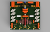
As promised, here are a couple of renderings:

driver_2020-Oct-18_04-46-26PM-000_CustomizedView100241097.png driver v14.png

(Sadly, due to issues with the software, most of the copper is hidden)
 
Back
Top Bottom