You are using an out of date browser. It may not display this or other websites correctly.
You should upgrade or use an alternative browser.
You should upgrade or use an alternative browser.
The Mighty Bogen MO-200A
- Thread starter dcgillespie
- Start date

 :thmbsp:


Two Tube Operation Tests
OK. Did a pre-check on the amplifier to gauge the outcome of using the original transformers in a push-pull setup only (just two output tubes per channel). So, 6 of the 8 output tubes were yanked, leaving just one amplifier to run on two output tubes. The load was changed to 16 ohms, and power was applied.
The Bogen wasn't real thrilled with this idea, which I didn't think it would be. No problems were noted at all under quiescent conditions, but with drive applied to the two output tubes installed, they became unstable rather quickly. I expected as much with such high Gm tubes -- now conducting twice the current under dynamic conditions than before -- and with all that "loose" wiring under the chassis too, not to mention back driving the other output transformer, with the output from its primary wiring radiating all over the place under the chassis as well. Also, I say loose wiring, not because any wiring was disconnected, but because there was wiring from the two tubes installed going over to the other two output tube sockets for that channel that had no tubes in them. So, there was effectively extra wiring attached to plate and grid terminals of the two tubes that were installed, but going nowhere -- which is an absolute disaster of instability waiting to happen with 8417 tubes. Still however, I was able to get two tubes in two of the sockets on one channel to remain stable, where upon basic tests were conducted.
No power supply modulation occurred this time since much less power was being drawn from the power supply. Therefore, full power 1 kHz sine waves advanced right up to a rather soft clip, without the "fill in" discussed earlier. The two output tubes at the onset of clipping developed 105 watts RMS (now into 16 ohms) -- almost exactly 1/2 of the power the as built amplifier produced before power supply modulation with 8 tubes installed -- which all by itself is pretty impressive, and speaks to the massive over-design of the unit. It was interesting to note however, that 8417 tubes won't do this after a typical 2 minute warmup time, but only after about 3 or 4 minutes of warm up. Before then, it struggles to produce about 90 watts. I have noted this effect before when working with 8417 tubes in the past. The ultra low quiescent current certainly doesn't help the tubes in this regard, either.
The power bandwidth on the low end suffered a little more relatively -- which was also to be expected because you now have twice the drive impedance presented to the transformer, which always reduces transformer low end performance. However, it wasn't that big of a drop, and we've already decided to go forward with these transformers anyway, so it makes whatever the difference is a rather moot point.
With that then, the idea will be to design for use with 6550 tubes. This will then allow for the greatest flexibility in tube rolling, but quite possibly require a new front end, as the existing design will be quite stretched in driving 6550 tubes to full power output. Before that can be determined however, tests need to be run as to the best way to apply feedback, how much feedback the transformer can handle, and whether cathode feedback is an option with these transformers. Past experience says it won't be, but you never know until you try.
Pics include:
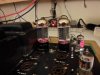
1. The two sockets that would produce stable operation with two tube operation. The others all "worked", but generally went unstable after as little as 10 watts of power was produced.
2. Nothing under the hood has changed at this point from the stock build. These two tubes are still idling at nearly the same low idle current -- although slightly higher now (about 20 ma each) because the draw of 6 output tubes (heater and B+) has been eliminated. The tubes in this shot are producing full power output as shown in the next shot.
3. 41 vac into 16 ohms equals 105 watts RMS. Notice too that with the higher quiescent current, the crossover distortion on this 1 kHz sine wave is nearly gone, too.
So, 1/2 rated power is available from just two tubes as the OPT primary winding dictated. More tests of course will follow.
Family is arriving for the holidays, and there are some other projects promised as well in the upcoming weeks, but work will creep forward on this project too during the holiday season.
Dave
OK. Did a pre-check on the amplifier to gauge the outcome of using the original transformers in a push-pull setup only (just two output tubes per channel). So, 6 of the 8 output tubes were yanked, leaving just one amplifier to run on two output tubes. The load was changed to 16 ohms, and power was applied.
The Bogen wasn't real thrilled with this idea, which I didn't think it would be. No problems were noted at all under quiescent conditions, but with drive applied to the two output tubes installed, they became unstable rather quickly. I expected as much with such high Gm tubes -- now conducting twice the current under dynamic conditions than before -- and with all that "loose" wiring under the chassis too, not to mention back driving the other output transformer, with the output from its primary wiring radiating all over the place under the chassis as well. Also, I say loose wiring, not because any wiring was disconnected, but because there was wiring from the two tubes installed going over to the other two output tube sockets for that channel that had no tubes in them. So, there was effectively extra wiring attached to plate and grid terminals of the two tubes that were installed, but going nowhere -- which is an absolute disaster of instability waiting to happen with 8417 tubes. Still however, I was able to get two tubes in two of the sockets on one channel to remain stable, where upon basic tests were conducted.
No power supply modulation occurred this time since much less power was being drawn from the power supply. Therefore, full power 1 kHz sine waves advanced right up to a rather soft clip, without the "fill in" discussed earlier. The two output tubes at the onset of clipping developed 105 watts RMS (now into 16 ohms) -- almost exactly 1/2 of the power the as built amplifier produced before power supply modulation with 8 tubes installed -- which all by itself is pretty impressive, and speaks to the massive over-design of the unit. It was interesting to note however, that 8417 tubes won't do this after a typical 2 minute warmup time, but only after about 3 or 4 minutes of warm up. Before then, it struggles to produce about 90 watts. I have noted this effect before when working with 8417 tubes in the past. The ultra low quiescent current certainly doesn't help the tubes in this regard, either.
The power bandwidth on the low end suffered a little more relatively -- which was also to be expected because you now have twice the drive impedance presented to the transformer, which always reduces transformer low end performance. However, it wasn't that big of a drop, and we've already decided to go forward with these transformers anyway, so it makes whatever the difference is a rather moot point.
With that then, the idea will be to design for use with 6550 tubes. This will then allow for the greatest flexibility in tube rolling, but quite possibly require a new front end, as the existing design will be quite stretched in driving 6550 tubes to full power output. Before that can be determined however, tests need to be run as to the best way to apply feedback, how much feedback the transformer can handle, and whether cathode feedback is an option with these transformers. Past experience says it won't be, but you never know until you try.
Pics include:
1. The two sockets that would produce stable operation with two tube operation. The others all "worked", but generally went unstable after as little as 10 watts of power was produced.
2. Nothing under the hood has changed at this point from the stock build. These two tubes are still idling at nearly the same low idle current -- although slightly higher now (about 20 ma each) because the draw of 6 output tubes (heater and B+) has been eliminated. The tubes in this shot are producing full power output as shown in the next shot.
3. 41 vac into 16 ohms equals 105 watts RMS. Notice too that with the higher quiescent current, the crossover distortion on this 1 kHz sine wave is nearly gone, too.
So, 1/2 rated power is available from just two tubes as the OPT primary winding dictated. More tests of course will follow.
Family is arriving for the holidays, and there are some other projects promised as well in the upcoming weeks, but work will creep forward on this project too during the holiday season.
Dave
Attachments



Hi jay -- Sensitivity remained essentially the same as before: 2.0 volts to produce 105 watts of power output -- since that is what each amplifier was producing before when both amplifiers were on line producing a total of (about) 215 watts.
However, because it was only one amplifier operating, the load was changed to 16 ohms, because that is in fact what the output impedance of each tap that is connected to the 8 ohm connection tap is. Two 16 ohm output impedance amplifiers of identical power connected in parallel produce an 8 ohm output of twice the power of one amplifier.
Dave
However, because it was only one amplifier operating, the load was changed to 16 ohms, because that is in fact what the output impedance of each tap that is connected to the 8 ohm connection tap is. Two 16 ohm output impedance amplifiers of identical power connected in parallel produce an 8 ohm output of twice the power of one amplifier.
Dave
Update
With the basic as built tests completed, moving forward on the big Bogen then required separating the two individual amplifiers into two separate channels, and neatly rewiring one of them to use as a development test bed. This needed to be done so that any build issues can be eliminated as a factor from the results of development testing. Since the end product will only use two output tubes per channel to produce 100 watts, that is the way the test bed was configured. Besides removing two output tubes then, the only other changes made so far is to replace the 30 ohm output tube balancing pot with two matched 10 ohm 1 watt resistors, and installing the NFB circuit of the MO100A amplifier, since the input stage common cathode resistor had to be changed to facilitate the separation. The clean up of the wiring already stopped the previous instability noted dead in its tracks. There is no longer any tendency towards producing parasitic oscillations as full power output is approached, and exceeded. This is all as observed from a 16 ohm load on the 16 ohm tap.
From this point now:
1. A proper DC balance control can be developed for the output stage -- one which works by varying the negative grid voltage applied to each output tube.
The original variable resistance in the cathode circuit of the output tubes works well enough to balance the tubes under quiescent conditions OR dynamic conditions, but does a poor job of trying to do both -- and whatever it does, it is done at the expense of power output. Bogen could use this approach because their quiescent current was set so low, that any setting still resulted in all the tubes idling extremely cool. Therefore, the control could be used to target dynamic balance, as supported by their instructions for setting the control.
In the process of developing a proper DC balance control, a bias control will also be added into the design. That way, the output stage can be biased and balanced for lowest possible distortion operation.
2. The R/C coupling into the output stage will be examined for maximum LF benefit, consistent with good LF stability.
3. An AC balance control can be provided to produce maximum distortion cancellation in the output stage.
4. Direct coupling between the AF amplifier stage and Phase Splitter stage can be investigated.
5. The existing NFB circuits can be examined for level and effectiveness, while new approaches can be evaluated for effectiveness as well. This would include efforts to maximize open loop gain (OLG), applying cathode feedback if possible in the output stage, and taking the existing global NFB from alternate output terminal connections.
Following through on these efforts then will allow the unit to operate most efficiently and effectively, based on the most basic circuit elements of what the original design represents.
Pics include:
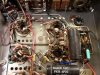
1. The amplifier area, with the amplifiers separated at the hip, and one cleaned up for development test purposes. The left amplifier is cleaned up and operational, while the right unit still represents the original build.
2. A close up of the amplifier cleaned up for development purposes.
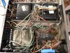
3. The power supply is still a complete mess, but plods along until I can clean it up. Also, taped up and out of the way are some of the output connections of the idled amplifier channel. Finally, the balanced 70 volt winding leads are also available to see if push-pull Cathode feedback can be effectively applied for any benefit.
With this, the Bogen will be set aside for a short period to follow through on a previous obligation. But when I return, making the best of the original design for home stereo use now can really begin in earnest.
Dave
With the basic as built tests completed, moving forward on the big Bogen then required separating the two individual amplifiers into two separate channels, and neatly rewiring one of them to use as a development test bed. This needed to be done so that any build issues can be eliminated as a factor from the results of development testing. Since the end product will only use two output tubes per channel to produce 100 watts, that is the way the test bed was configured. Besides removing two output tubes then, the only other changes made so far is to replace the 30 ohm output tube balancing pot with two matched 10 ohm 1 watt resistors, and installing the NFB circuit of the MO100A amplifier, since the input stage common cathode resistor had to be changed to facilitate the separation. The clean up of the wiring already stopped the previous instability noted dead in its tracks. There is no longer any tendency towards producing parasitic oscillations as full power output is approached, and exceeded. This is all as observed from a 16 ohm load on the 16 ohm tap.
From this point now:
1. A proper DC balance control can be developed for the output stage -- one which works by varying the negative grid voltage applied to each output tube.
The original variable resistance in the cathode circuit of the output tubes works well enough to balance the tubes under quiescent conditions OR dynamic conditions, but does a poor job of trying to do both -- and whatever it does, it is done at the expense of power output. Bogen could use this approach because their quiescent current was set so low, that any setting still resulted in all the tubes idling extremely cool. Therefore, the control could be used to target dynamic balance, as supported by their instructions for setting the control.
In the process of developing a proper DC balance control, a bias control will also be added into the design. That way, the output stage can be biased and balanced for lowest possible distortion operation.
2. The R/C coupling into the output stage will be examined for maximum LF benefit, consistent with good LF stability.
3. An AC balance control can be provided to produce maximum distortion cancellation in the output stage.
4. Direct coupling between the AF amplifier stage and Phase Splitter stage can be investigated.
5. The existing NFB circuits can be examined for level and effectiveness, while new approaches can be evaluated for effectiveness as well. This would include efforts to maximize open loop gain (OLG), applying cathode feedback if possible in the output stage, and taking the existing global NFB from alternate output terminal connections.
Following through on these efforts then will allow the unit to operate most efficiently and effectively, based on the most basic circuit elements of what the original design represents.
Pics include:
1. The amplifier area, with the amplifiers separated at the hip, and one cleaned up for development test purposes. The left amplifier is cleaned up and operational, while the right unit still represents the original build.
2. A close up of the amplifier cleaned up for development purposes.
3. The power supply is still a complete mess, but plods along until I can clean it up. Also, taped up and out of the way are some of the output connections of the idled amplifier channel. Finally, the balanced 70 volt winding leads are also available to see if push-pull Cathode feedback can be effectively applied for any benefit.
With this, the Bogen will be set aside for a short period to follow through on a previous obligation. But when I return, making the best of the original design for home stereo use now can really begin in earnest.
Dave
Attachments
Yes, and at the DC voltage level they work at versus their 600 volt rating, none of them leak at all in this amp, either. I haven't run them up to their rated voltage to test to test for absolute leakage, but at this point in the development process, there is no reason to change them out for any leakage concerns.
Dave
Dave


rockur
Active Member
Seems to be a CHB 50
50 watts.
After a little searching around I find that it's well regarded by some in the guitar amp world. One sold on Canuck Audio for $600 back in 2011!
Complete tube noob here...
:thmbsp:
I have a CHB 100 in hand. Solid construction, but guess what, I've never light it up! I bought it quite long time ago just because it was a bogen, being an owner of a DB 20 for age

rockur
Active Member
Yes, and at the DC voltage level they work at versus their 600 volt rating, none of them leak at all in this amp, either. I haven't run them up to their rated voltage to test to test for absolute leakage, but at this point in the development process, there is no reason to change them out for any leakage concerns.
Dave
I'm sure a lot of BC caps addicted would gladly use any "used" caps in there for a cap replacement for there own tube amps not equiped with those.
rockur
Active Member
I thought you were being sarcastic about the Black Cat caps. I've tossed lots of those things. Most of them were leaky and useless when I've come across them.
Not at all hehe.. you could almost compare this to uk mullard tubes... of course when they're checking good. A good BC cap is valuable in my books.


This has potential, given the experience with the Eico ST70,
Split, there is the opportunity of running the 16 ohm tap as an 8 ohm tap per channel (i.,e, split the transformers, but continue to use the tap for 8 ohms as 8 ohms, instead of scaling to 16 ohms). That would reduce the effective primary impedance to 2375 ohms- which could be good for PPP EL34s, PPP6550/KT88s, or even PPP 6L6GCs in Class A.
In fact, here's a 6L6GC alignment that would be pretty close:
Push Pull Class AB1 Amplifier
Source ........................................ Sylvania - 1959
Plate Voltage ................................. 330 V
Grid No. 2 Voltage ............................ 330 V
Grid No. 1 Voltage ............................ -24 V
Peak Grid No. 1 Voltage........................ 48 V
Plate Current (Zero Signal) ................... 122 mA
Plate Current (Maximum Signal) ................ 184 mA
Grid No. 2 Current (Zero Signal) .............. 5 mA
Grid No. 2 Current (Maximum Signal) ........... 11 mA
Load Resistance ............................... 3.8K Ω
Power Output (approx) ......................... 31.5 W
That's from one pair- two pairs, with slightly higher OPT impedance (effectively 4.75K per pair) and slightly lower B+ (see below) , should still be able to produce 50 watts easy...
If either EL34s or 6L6s were used, the reduced total heater current draw would allow a second driver/inverter tube to be added, for each channel. That would allow the use of either Williamson or Mullard front end designs...
BTW: I'm assuming the MO200 has the same type of voltage-doubler power supply as the MO60? If so, I wonder if it might be good to UN-double it- just make a MASSIVE current supply, at around maybe 310v or so? The resultant amp would wind up probably around 50w/ch or so- but it'd be the stoutest 50 watts imaginable, probably...
Regards,
Gordon.
Split, there is the opportunity of running the 16 ohm tap as an 8 ohm tap per channel (i.,e, split the transformers, but continue to use the tap for 8 ohms as 8 ohms, instead of scaling to 16 ohms). That would reduce the effective primary impedance to 2375 ohms- which could be good for PPP EL34s, PPP6550/KT88s, or even PPP 6L6GCs in Class A.
In fact, here's a 6L6GC alignment that would be pretty close:
Push Pull Class AB1 Amplifier
Source ........................................ Sylvania - 1959
Plate Voltage ................................. 330 V
Grid No. 2 Voltage ............................ 330 V
Grid No. 1 Voltage ............................ -24 V
Peak Grid No. 1 Voltage........................ 48 V
Plate Current (Zero Signal) ................... 122 mA
Plate Current (Maximum Signal) ................ 184 mA
Grid No. 2 Current (Zero Signal) .............. 5 mA
Grid No. 2 Current (Maximum Signal) ........... 11 mA
Load Resistance ............................... 3.8K Ω
Power Output (approx) ......................... 31.5 W
That's from one pair- two pairs, with slightly higher OPT impedance (effectively 4.75K per pair) and slightly lower B+ (see below) , should still be able to produce 50 watts easy...
If either EL34s or 6L6s were used, the reduced total heater current draw would allow a second driver/inverter tube to be added, for each channel. That would allow the use of either Williamson or Mullard front end designs...
BTW: I'm assuming the MO200 has the same type of voltage-doubler power supply as the MO60? If so, I wonder if it might be good to UN-double it- just make a MASSIVE current supply, at around maybe 310v or so? The resultant amp would wind up probably around 50w/ch or so- but it'd be the stoutest 50 watts imaginable, probably...
Regards,
Gordon.
OK, so this thread may not die just yet. After some back and forth with Rpampt, I sensed he wasn't ready to roll over on these yet, so I suggested we go forward and split the channels, and make this sucker be the best it can be with the transformers its got -- which is the agreement at hand. Afterall, if we start improving it to the quality of the Dynacos, then he basically just ends up with more Dynacos, which is really silly because he already has those. So, we'll go after these things as they are, to make them the best of what they are -- but with a re-purpose in mind for home stereo use -- and, knowing what we're starting from to begin with.
Stay tuned!
Dave
One other option, would be Class AB2, with PPP 6L6GCs.
A good front end (Williamson, probably), with something like the Tubelab "Powerdrive" circuit (essentially a solid-state source-follower buffer module) between it and the output tubes- and you could run Class AB2. With about 310v on the plates, I'd bet you could easily get 60-70 watts per channel that way. With the PS undoubled, there's be probably no way you'd ever run out of PS transformer current...
Regards,
Gordon.
A good front end (Williamson, probably), with something like the Tubelab "Powerdrive" circuit (essentially a solid-state source-follower buffer module) between it and the output tubes- and you could run Class AB2. With about 310v on the plates, I'd bet you could easily get 60-70 watts per channel that way. With the PS undoubled, there's be probably no way you'd ever run out of PS transformer current...
Regards,
Gordon.
Hi Gordon -- Thanks for chiming in with your excellent thoughts.
With a sky's the limit approach, so many things are possible with this unit, including upgrading the OPTs to better units as well.
The OPT's capabilities were already being extended somewhat in the original design, by using four output tubes to operate into a load normally offered for just two such tubes. The reduced drive impedance provided to the OPT then improved low end power response, and extended the life of the tubes for the operating conditions this unit was designed to work under -- which was sustained full power output for hours on end. This unit has outputs to operate shaker tables and the like, in addition to the usual sound distribution outputs, and traditional output impedance taps as well. There's a lot of windings in these transformers that establish basic practical limits that can be had. Still, with a full power bandwidth of 30 Hz to 10 kHz (which covers the vast majority of audible frequencies for most of us) , the goal for this particular unit is defined by seeing just how well this unit -- within what its original design and topology offered -- can be modified for traditional home stereo use. Even within that framework, there should be ample improvement to be had over simply splitting the two internal amplifiers apart, and of course, it can always be taken further.
This unit is going to end up going head to head against a pair of rather stock Dynaco MK IIIs, so the results will be interesting simply in and of that comparison alone, while the information offered along the way will hopefully help those who have either the same, or even greater ambitions for their units.
Dave
With a sky's the limit approach, so many things are possible with this unit, including upgrading the OPTs to better units as well.
The OPT's capabilities were already being extended somewhat in the original design, by using four output tubes to operate into a load normally offered for just two such tubes. The reduced drive impedance provided to the OPT then improved low end power response, and extended the life of the tubes for the operating conditions this unit was designed to work under -- which was sustained full power output for hours on end. This unit has outputs to operate shaker tables and the like, in addition to the usual sound distribution outputs, and traditional output impedance taps as well. There's a lot of windings in these transformers that establish basic practical limits that can be had. Still, with a full power bandwidth of 30 Hz to 10 kHz (which covers the vast majority of audible frequencies for most of us) , the goal for this particular unit is defined by seeing just how well this unit -- within what its original design and topology offered -- can be modified for traditional home stereo use. Even within that framework, there should be ample improvement to be had over simply splitting the two internal amplifiers apart, and of course, it can always be taken further.
This unit is going to end up going head to head against a pair of rather stock Dynaco MK IIIs, so the results will be interesting simply in and of that comparison alone, while the information offered along the way will hopefully help those who have either the same, or even greater ambitions for their units.
Dave
Output Stage Considerations
While it may look macho to have push-pull-parallel amps powering each channel, and may even help to supplement your furnace in the winter time, in this case, it makes little sense to maintain 4 output tubes per channel when re-purposing the MO-200A for stereo operation in the home. Consider that:
1. It produces no greater power output with four tubes per channel than it does with two,
2. There is the obvious increase in cost for the extra tubes, along with the attendant matching fees, and
3. The circuit is made necessarily more complicated if maximum performance is to be extracted from a push-pull-parallel output stage configuration.
Based on these considerations, and along with the revised use environment, it was decided to develop and ultimately operate each channel with only two output tubes.
At this point then, the output stage for the development channel has been modified to a more traditional two tube configuration:
1. The cathode Balance Adjustment pot has been removed, and two precision 10 ohm 1 watt resistors have been installed from each cathode to ground.
2. The 3 screw terminal strip originally used for supplying a balanced low impedance input signal to the amplifier has been re-purposed as test points now to monitor the current draw of each output tube via their respective 10 ohm cathode resistor.
3. A proper DC Balance Control has been provided (in the original Balance Control location) to raise the negative bias voltage to one tube, while simultaneously lowering it to the other.
4. The level control has been removed and replaced with a new Bias Control that -- once the DC Balance Control is set -- simultaneously moves both output tubes up or down in quiescent current draw, so that the DC balance is maintained while the lowest distortion operation point is determined.
Both the DC Balance and Bias controls have been designed with a fail safe mode in mind. That is, if the wiper of either control should lift from its carbon track, then the negative bias voltage will increase to each output tube to reduce current draw in the tubes.
5. The grid return resistors for the output stage were increased from 22K to 47K.
With these modifications installed, tests could then be run to determine power supply performance, as well as optimum quiescent current draw for the output stage.
At an output of 100 watts RMS at 1 kHz, as delivered into a 16 ohm load from the 16 ohm load tap, the optimum quiescent current draw setting (determined by that setting which returned the lowest distortion) was found to be 50 ma per tube. This lowered distortion from the original design -- where in both amplifiers before returned a combined 200 watt THD level of 1.65% -- down to 1.10%, for a 33% reduction in distortion. However, with the wickedly high plate B+ available in this amplifier (710 vdc under quiescent conditions with just one channel installed), this current level produced a static plate dissipation of 35 watts per tube, which is right at this tube's limit. Using a more practical 40 ma of quiescent current per tube, distortion only rose from its low point to 1.20%, while dissipation was reduced to 27 watts per tube, or 77% of plate dissipation rating.
At this quiescent current level (40 ma), all traces of the former Crossover Distortion were gone, while the increased level in LF NFB afforded by the increase in grid return resistor value (along with the increased quiescent current) also helped in increasing available LF power output: With the increase in quiescent current draw and improved LF coupling into the output stage, there is now a very usable 60 watts RMS available at 20 Hz from the modified amplifier. You may recall that the effective 20 Hz power output available from each individual amplifier in the original design was 54 watts RMS (108 watts total for both amplifiers) -- and this with the advantage that four output tubes per channel afforded in lowered drive impedance to the OPT primary winding. There was a similar improvement noted at 20 kHz as well.
Power supply performance is a problem however. Regulation for the plate B+ supply is very good at 5% -- which it should be with just one amplifier pulling power from a two amplifier power supply. However, regulation of the screen voltage was very poor at 12% -- which is always problematic for a pentode output stage, and undoubtedly is the cause of the still over 1% THD readings at 1 kHz at full power output. The screen voltage regulation and resulting distortion performance could only get much worst with two amplifiers drawing a full head of steam.
Options are being investigated to address the screen regulation issue. Use of a choke in place of the existing dropping/filter resistor might work, but installing EFB would be ideal, and lower distortion levels dramatically.
So, installation of proper DC Bias and Balance controls and appropriate cathode resistor/monitoring test points certainly aid in achieving maximum OPT performance and lowering distortion from the use of less than ideally matched tubes, and increasing the quiescent current to 40 ma per tube both have a very worthwhile effect in moving this beast towards its new intended use. The improved LF coupling into the output stage produced no tendency towards LF instability under any conditions of loading. This of course will be examined much more closely when the NFB system is examined in earnest. For all of the tests conducted to far, the original NFB loop -- as appropriate for a single amplifier (MO100A) -- is still in place.
Pics include:
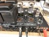
1. External view of the new DC Balance Control mounted in the old Balance control location. Also visible is the new Bias control in the old level control location. The 3-Terminal strip above it is now re-purposed to monitor output stage current draw.
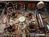
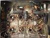
2. The underside view of the modified MO-200A as it now stands. At this point, this sucker is just a development mule, so parts used are whatever I can lay my hands on that will work at the moment.
Next up: Installing an AC Balance control to take care of any imbalance in the OPT and output stage, and taking a look at the screen regulation problem.
Dave
While it may look macho to have push-pull-parallel amps powering each channel, and may even help to supplement your furnace in the winter time, in this case, it makes little sense to maintain 4 output tubes per channel when re-purposing the MO-200A for stereo operation in the home. Consider that:
1. It produces no greater power output with four tubes per channel than it does with two,
2. There is the obvious increase in cost for the extra tubes, along with the attendant matching fees, and
3. The circuit is made necessarily more complicated if maximum performance is to be extracted from a push-pull-parallel output stage configuration.
Based on these considerations, and along with the revised use environment, it was decided to develop and ultimately operate each channel with only two output tubes.
At this point then, the output stage for the development channel has been modified to a more traditional two tube configuration:
1. The cathode Balance Adjustment pot has been removed, and two precision 10 ohm 1 watt resistors have been installed from each cathode to ground.
2. The 3 screw terminal strip originally used for supplying a balanced low impedance input signal to the amplifier has been re-purposed as test points now to monitor the current draw of each output tube via their respective 10 ohm cathode resistor.
3. A proper DC Balance Control has been provided (in the original Balance Control location) to raise the negative bias voltage to one tube, while simultaneously lowering it to the other.
4. The level control has been removed and replaced with a new Bias Control that -- once the DC Balance Control is set -- simultaneously moves both output tubes up or down in quiescent current draw, so that the DC balance is maintained while the lowest distortion operation point is determined.
Both the DC Balance and Bias controls have been designed with a fail safe mode in mind. That is, if the wiper of either control should lift from its carbon track, then the negative bias voltage will increase to each output tube to reduce current draw in the tubes.
5. The grid return resistors for the output stage were increased from 22K to 47K.
With these modifications installed, tests could then be run to determine power supply performance, as well as optimum quiescent current draw for the output stage.
At an output of 100 watts RMS at 1 kHz, as delivered into a 16 ohm load from the 16 ohm load tap, the optimum quiescent current draw setting (determined by that setting which returned the lowest distortion) was found to be 50 ma per tube. This lowered distortion from the original design -- where in both amplifiers before returned a combined 200 watt THD level of 1.65% -- down to 1.10%, for a 33% reduction in distortion. However, with the wickedly high plate B+ available in this amplifier (710 vdc under quiescent conditions with just one channel installed), this current level produced a static plate dissipation of 35 watts per tube, which is right at this tube's limit. Using a more practical 40 ma of quiescent current per tube, distortion only rose from its low point to 1.20%, while dissipation was reduced to 27 watts per tube, or 77% of plate dissipation rating.
At this quiescent current level (40 ma), all traces of the former Crossover Distortion were gone, while the increased level in LF NFB afforded by the increase in grid return resistor value (along with the increased quiescent current) also helped in increasing available LF power output: With the increase in quiescent current draw and improved LF coupling into the output stage, there is now a very usable 60 watts RMS available at 20 Hz from the modified amplifier. You may recall that the effective 20 Hz power output available from each individual amplifier in the original design was 54 watts RMS (108 watts total for both amplifiers) -- and this with the advantage that four output tubes per channel afforded in lowered drive impedance to the OPT primary winding. There was a similar improvement noted at 20 kHz as well.
Power supply performance is a problem however. Regulation for the plate B+ supply is very good at 5% -- which it should be with just one amplifier pulling power from a two amplifier power supply. However, regulation of the screen voltage was very poor at 12% -- which is always problematic for a pentode output stage, and undoubtedly is the cause of the still over 1% THD readings at 1 kHz at full power output. The screen voltage regulation and resulting distortion performance could only get much worst with two amplifiers drawing a full head of steam.
Options are being investigated to address the screen regulation issue. Use of a choke in place of the existing dropping/filter resistor might work, but installing EFB would be ideal, and lower distortion levels dramatically.
So, installation of proper DC Bias and Balance controls and appropriate cathode resistor/monitoring test points certainly aid in achieving maximum OPT performance and lowering distortion from the use of less than ideally matched tubes, and increasing the quiescent current to 40 ma per tube both have a very worthwhile effect in moving this beast towards its new intended use. The improved LF coupling into the output stage produced no tendency towards LF instability under any conditions of loading. This of course will be examined much more closely when the NFB system is examined in earnest. For all of the tests conducted to far, the original NFB loop -- as appropriate for a single amplifier (MO100A) -- is still in place.
Pics include:
1. External view of the new DC Balance Control mounted in the old Balance control location. Also visible is the new Bias control in the old level control location. The 3-Terminal strip above it is now re-purposed to monitor output stage current draw.
2. The underside view of the modified MO-200A as it now stands. At this point, this sucker is just a development mule, so parts used are whatever I can lay my hands on that will work at the moment.
Next up: Installing an AC Balance control to take care of any imbalance in the OPT and output stage, and taking a look at the screen regulation problem.
Dave