

You are using an out of date browser. It may not display this or other websites correctly.
You should upgrade or use an alternative browser.
You should upgrade or use an alternative browser.
The Mighty Bogen MO-200A
- Thread starter dcgillespie
- Start date


Something I did notice in my 100a's, those 22k resistors are actually 2% precision resistors, not the common 10% carbon comps used everywhere else. It seems they were going to a bit of trouble to try and assure symmetrical output from the phase inverter. Odd that with all that bother to use good parts, they were using it on a design that was comprimised from the start. I'm not sure exactly how much you've altered it from the original design but it doesn't seem like it would have been a huge change to the basic circuit to yield rather better performance right out of the door.


Here's an easy way to solve this issue that requires no engineering effort: Reprint the documentation to state a lower power output than originally expected!  I'm sure the marketing department at Bogen would not have taken kindly to that approach. (I'm just kidding of course.)
  .
.
But it does seem to me a proper design would allow the front-end and driver stages to run clean, up to max power, under any conditions, so that the output stage clips first before the driver or frontend stages go non linear--at least in a hi-fi amp. That appears to be easier said than done, as some quite experienced engineers, I'm sure, apparently missed it on this original design.
Note to self: Go back and check my own work to see if I've made the same mistake!!
I'm sure the marketing department at Bogen would not have taken kindly to that approach. (I'm just kidding of course.) .But it does seem to me a proper design would allow the front-end and driver stages to run clean, up to max power, under any conditions, so that the output stage clips first before the driver or frontend stages go non linear--at least in a hi-fi amp. That appears to be easier said than done, as some quite experienced engineers, I'm sure, apparently missed it on this original design.
Note to self: Go back and check my own work to see if I've made the same mistake!!

I completely agree with both of you. The use of 2% matched parts in both the phase inverter AND the grid return portion of the output stage certainly shows an attention to detail in maintaining dynamic balance -- AND -- Bogen was not that clueless.
I've tried to come at this every which way that I can -- from out of spec components (nope), to non spec tubes (nope), to schematic misprints and inaccuracies (?). The remaining components installed are well within spec, the tubes are all very good old stock tubes, and the original design as I received it, did meet specifications for power and distortion as published by Bogen for this model.
In racking my brain over it all, the ONLY thing that makes any sense, is that these units were never designed -- or intended -- to do what we are now trying to make them do. They were very good utility amplifiers (with power of these type units typically rated at 5% THD -- not a more conservative 2% as Bogen did), that were designed for extended operation and long tube life. With rated power delivered with no more than 2% THD, it was all good, and just quite possibly, there was no reason to correct the design, as it was likely already producing a cleaner output waveform than many of it competitor's unit were.
Remember too, all of this came to light in trying to make this amplifier do something it was not designed to do. Since it did in fact perform as it was designed to do when received, Bogen basically has nothing to apologize for -- except that the design of the input stage -- regardless of use application -- is lame, and could have been corrected so easily......
In any event, the next stop in the hunt for lower distortion is the power supply section, and then stabilizing the new feedback network developed to produce absolute stability.
Finally, one thing appears rather certain at this point. For those who want to make the best of these units with minimum change, cost, or work, then they should strongly consider retaining use of the original output tubes.
While the driver circuit is capable of driving other more common output tubes (primarily EL34), it will significantly affect input sensitivity requirements if the same performance as that delivered by 8417 tubes is to be retained. The 8417 has proven to be a very stout tube, but again, other output tubes can be used. To do that job properly however -- even with EL34s -- will require development of a new front end driver design. Just some thoughts that appear to be jelling up for your consideration.
Dave
I've tried to come at this every which way that I can -- from out of spec components (nope), to non spec tubes (nope), to schematic misprints and inaccuracies (?). The remaining components installed are well within spec, the tubes are all very good old stock tubes, and the original design as I received it, did meet specifications for power and distortion as published by Bogen for this model.
In racking my brain over it all, the ONLY thing that makes any sense, is that these units were never designed -- or intended -- to do what we are now trying to make them do. They were very good utility amplifiers (with power of these type units typically rated at 5% THD -- not a more conservative 2% as Bogen did), that were designed for extended operation and long tube life. With rated power delivered with no more than 2% THD, it was all good, and just quite possibly, there was no reason to correct the design, as it was likely already producing a cleaner output waveform than many of it competitor's unit were.
Remember too, all of this came to light in trying to make this amplifier do something it was not designed to do. Since it did in fact perform as it was designed to do when received, Bogen basically has nothing to apologize for -- except that the design of the input stage -- regardless of use application -- is lame, and could have been corrected so easily......
In any event, the next stop in the hunt for lower distortion is the power supply section, and then stabilizing the new feedback network developed to produce absolute stability.
Finally, one thing appears rather certain at this point. For those who want to make the best of these units with minimum change, cost, or work, then they should strongly consider retaining use of the original output tubes.
While the driver circuit is capable of driving other more common output tubes (primarily EL34), it will significantly affect input sensitivity requirements if the same performance as that delivered by 8417 tubes is to be retained. The 8417 has proven to be a very stout tube, but again, other output tubes can be used. To do that job properly however -- even with EL34s -- will require development of a new front end driver design. Just some thoughts that appear to be jelling up for your consideration.
Dave

nj pheonix
Lunatic Member
Dave ,
I think you hit it on the head. 50 years after the fact. Probably working 24-7 for many years. It meets spec. Better than its competition. Why spend more money on engineering? I'm thinking the 2% resistors just gave it a touch more stability.
Considering the driver stage, its beyond my knowledge base. Based on value of the 8417s it might be cheaper to redesign the driver for El34s and finance the project with the sale of the tubes. Then again you have a 4 surplus now.
I think you hit it on the head. 50 years after the fact. Probably working 24-7 for many years. It meets spec. Better than its competition. Why spend more money on engineering? I'm thinking the 2% resistors just gave it a touch more stability.
Considering the driver stage, its beyond my knowledge base. Based on value of the 8417s it might be cheaper to redesign the driver for El34s and finance the project with the sale of the tubes. Then again you have a 4 surplus now.

jaymanaa
RIP 1961-2018
Allen Organ and Scott HiFi had no problem making changes to the circuit without updating the schematics too. At least not in a timely fashion. Thanks for posting this Dave. Most all the testing you do, is something that a lot of us won't have to do now. Thanks for sharing that brain power, I need all the help I can find. :yes:

rockur
Active Member
...In racking my brain over it all, the ONLY thing that makes any sense, is that these units were never designed -- or intended -- to do what we are now trying to make them do. They were very good utility amplifiers (with power of these type units typically rated at 5% THD -- not a more conservative 2% as Bogen did), that were designed for extended operation and long tube life. With rated power delivered with no more than 2% THD, it was all good, and just quite possibly, there was no reason to correct the design, as it was likely already producing a cleaner output waveform than many of it competitor's unit were...
It's funny. As far as I'm concerned, too perfect amps with something like 0.005% THD have not remain long in my home listening world. I always found smoother to my ears the sound of amplifiers with 0.5% and up THD (2-3% about max) which were for most, pre-1975 production units including tube amps. The components used at the time surely plays a role. Seeing that, after 50-60 years, they're still withing specs, in the case of that bogen, we can call this reliability.
jaymanaa
RIP 1961-2018
It's funny. As far as I'm concerned, too perfect amps with something like 0.005% THD have not remain long in my home listening world. I always found smoother to my ears the sound of amplifiers with 0.5% and up THD (2-3% about max) which were for most, pre-1975 production units including tube amps. The components used at the time surely plays a role. Seeing that, after 50-60 years, they're still withing specs, in the case of that bogen, we can call this reliability.
I think this is why SET amps are so popular maybe.
Rock -- In the end, I completely agree with your assessment -- but for myself, I would offer an alternate reason as to why: I don't believe it is the lack of distortion so much (i.e. the .0000000x% THD levels) that is so dissatisfying, but rather, the method in which it is achieved.
Equipment with ultra low distortion levels contain massive amounts of NFB. While I absolutely believe in the merits that it offers, I am decidedly NOT in the crowd that if some NFB is good, more is better. I believe that there is a very defined point after which adding more feedback does nothing by dry out the sound, leaving it lifeless. However, even if the level is correct, feedback must also be applied in a stable fashion, or the effects of instability can become very audible.
To that point then, all of my efforts with the Bogen to date still use the original design level of 17 db NFB,(altered slightly only by the increase in quiescent current now used), with all of the distortion reduction occurring because of improved AC/DC balance, improved operating points, and improved use of the existing feedback level. Achieving reductions in distortion in this manner have always been far more preferable to me, rather than simply throwing more feedback at a design to cover up its warts.
Dave
Equipment with ultra low distortion levels contain massive amounts of NFB. While I absolutely believe in the merits that it offers, I am decidedly NOT in the crowd that if some NFB is good, more is better. I believe that there is a very defined point after which adding more feedback does nothing by dry out the sound, leaving it lifeless. However, even if the level is correct, feedback must also be applied in a stable fashion, or the effects of instability can become very audible.
To that point then, all of my efforts with the Bogen to date still use the original design level of 17 db NFB,(altered slightly only by the increase in quiescent current now used), with all of the distortion reduction occurring because of improved AC/DC balance, improved operating points, and improved use of the existing feedback level. Achieving reductions in distortion in this manner have always been far more preferable to me, rather than simply throwing more feedback at a design to cover up its warts.
Dave
jaymanaa
RIP 1961-2018
Rock -- In the end, I completely agree with your assessment -- but for myself, I would offer an alternate reason as to why: I don't believe it is the lack of distortion so much (i.e. the .0000000x% THD levels) that is so dissatisfying, but rather, the method in which it is achieved.
Equipment with ultra low distortion levels contain massive amounts of NFB. While I absolutely believe in the merits that it offers, I am decidedly NOT in the crowd that if some NFB is good, more is better. I believe that there is a very defined point after which adding more feedback does nothing by dry out the sound, leaving it lifeless. However, even if the level is correct, feedback must also be applied in a stable fashion, or the effects of instability can become very audible.
To that point then, all of my efforts with the Bogen to date still use the original design level of 17 db NFB,(altered slightly only by the increase in quiescent current now used), with all of the distortion reduction occurring because of improved AC/DC balance, improved operating points, and improved use of the existing feedback level. Achieving reductions in distortion in this manner have always been far more preferable to me, rather than simply throwing more feedback at a design to cover up its warts.
Dave
That's what they do with SS amps. Try one of those without the 1.5 metric tons of feedback they use. It's ok though, because power and gain are pretty cheap in SS.
rockur
Active Member
... I am decidedly NOT in the crowd that if some NFB is good, more is better. I believe that there is a very defined point after which adding more feedback does nothing by dry out the sound, leaving it lifeless.
So well said and exactly my point. That's why I just can't get used to most post-1980 systems to generalize.
Update
To finish up the distortion reduction effort, it was determined -- now that the output stage is getting a clean, undistorted, and equal drive signal right up to the point of clipping -- that the optimum quiescent current for the output stage is really more on the order of 60 ma per tube, rather than the 50 ma previously stated -- the error coming from the poor, unequal drive presented to the output stage at the time of the original determination.
This is more in keeping with theory, since these tubes would normally want a quiescent current of about 50 ma. However, a sinking screen voltage with increasing power output requires a higher quiescent current, so that when the screen voltage does fall, the optimum quiescent current is then produced under dynamic conditions. That's why starting with 50 ma in the first place was ultimately shown to be erroneous when a proper drive signal was applied: it sank further from there as power was increased, and starting from 40 ma made it even worse. So again, with the proper drive conditions now in place, AND THE POWER SUPPLY CONDITIONS AT HAND, 60 ma is the ideal quiescent current.
But 60 ma per tube will well exceed the rated plate dissipation for the tubes, so operating the output stage at the optimum quiescent current won't work. And there's more.
The screen grid voltage regulation has been identified as a problem, with fixing it being the last stop on the distortion reduction effort. But regulating it gets involved due to the high current demand (50 ma per channel), and regulating it at any higher voltage value that it currently drops to under full power conditions will cause the screens to exceed their dissipation rating as well.
The answer to all of this is to operate the output stage under the control of EFB(tm). This will allow the screen grid voltage to fall as necessary so that screen dissipation limits are maintained, but also adjust the negative grid voltage so that as the screen voltage falls, the grid bias voltage falls accordingly as well, which will then effectively throw the low distortion operating point back down well within the plate dissipation rating of the tube. This is what EFB does best, and it should be quite effective in this application. It should also be a rather simple installation too, since a screen grid EFB regulator likely won't be required.
With the game plan in place to achieve last bit of the distortion reduction then, the more immediate plan is to get a handle on stabilizing the new feedback network. Again, the network will not use any more feedback than the original did, but it will be a completely different configuration, which along with the modifications made to the AF amplifier stage, will also be much more effective. It is also anticipated that the frequency response and resulting square wave response will improve immensely as well.
So, these are the last two areas of development relating to the original design. The feedback network will be tackled first, with EFB being the last element, since it is a known capability. When these are finished, then it's time for some final performance testing, noise testing, and ultimately, some sonic testing!
Dave
To finish up the distortion reduction effort, it was determined -- now that the output stage is getting a clean, undistorted, and equal drive signal right up to the point of clipping -- that the optimum quiescent current for the output stage is really more on the order of 60 ma per tube, rather than the 50 ma previously stated -- the error coming from the poor, unequal drive presented to the output stage at the time of the original determination.
This is more in keeping with theory, since these tubes would normally want a quiescent current of about 50 ma. However, a sinking screen voltage with increasing power output requires a higher quiescent current, so that when the screen voltage does fall, the optimum quiescent current is then produced under dynamic conditions. That's why starting with 50 ma in the first place was ultimately shown to be erroneous when a proper drive signal was applied: it sank further from there as power was increased, and starting from 40 ma made it even worse. So again, with the proper drive conditions now in place, AND THE POWER SUPPLY CONDITIONS AT HAND, 60 ma is the ideal quiescent current.
But 60 ma per tube will well exceed the rated plate dissipation for the tubes, so operating the output stage at the optimum quiescent current won't work. And there's more.
The screen grid voltage regulation has been identified as a problem, with fixing it being the last stop on the distortion reduction effort. But regulating it gets involved due to the high current demand (50 ma per channel), and regulating it at any higher voltage value that it currently drops to under full power conditions will cause the screens to exceed their dissipation rating as well.
The answer to all of this is to operate the output stage under the control of EFB(tm). This will allow the screen grid voltage to fall as necessary so that screen dissipation limits are maintained, but also adjust the negative grid voltage so that as the screen voltage falls, the grid bias voltage falls accordingly as well, which will then effectively throw the low distortion operating point back down well within the plate dissipation rating of the tube. This is what EFB does best, and it should be quite effective in this application. It should also be a rather simple installation too, since a screen grid EFB regulator likely won't be required.
With the game plan in place to achieve last bit of the distortion reduction then, the more immediate plan is to get a handle on stabilizing the new feedback network. Again, the network will not use any more feedback than the original did, but it will be a completely different configuration, which along with the modifications made to the AF amplifier stage, will also be much more effective. It is also anticipated that the frequency response and resulting square wave response will improve immensely as well.
So, these are the last two areas of development relating to the original design. The feedback network will be tackled first, with EFB being the last element, since it is a known capability. When these are finished, then it's time for some final performance testing, noise testing, and ultimately, some sonic testing!
Dave
Last edited:

Picture about 100 of these Quams in the ceilings tapped at 1/8 of a watt, using the 70 volt output at a listening level just loud enough that you can hear it over the normal background noise of a crowded department story. running all day and all night the Bogen was just right! No extended frequency ranges needed, the distortion would be unable to detect, and for the most part probably trouble free, you really couldn't have asked more from them.
But it sure would be nice if we could all hear what your able to get out of it after you reconfigure it to be a good device for home audio. Maybe I need to work at getting a better sound card for my PC.
 just right! No extended frequency ranges needed, the distortion would be unable to detect, and for the most part probably trouble free, you really couldn't have asked more from them.
But it sure would be nice if we could all hear what your able to get out of it after you reconfigure it to be a good device for home audio. Maybe I need to work at getting a better sound card for my PC.
Rounding Third For Home!
With the work on the NFB loop now complete, that basically finishes up the redesign of the amplifier proper, leaving only the power supply, and the installation of EFB as items left to address.
In review then:
1. Each channel now operates with only two output tubes, producing just as much power as the original design did with four tubes (per amplifier).
2. The output stage has been fitted with individual cathode sampling resistors, and DC bias and balance controls to effect a close DC balance at the required quiescent current.
3. A new quiescent current has been established for the output stage to operate at, but this will be revisited again with the installation of EFB.
4. The coupling cap time constant between the inverter and output stage has been revised.
5. The phase inverter stage has had an AC balance control installed.
6. The input AF amplifier stage now operates with more static bias to maintain linearity of drive signals between the outputs of the phase inverter stage, as elevated power output levels are reached.
7. A new NFB loop and stability circuits have been developed that maintains the original measured 17 db of NFB, while maintaining complete stability under all conceivable loading conditions. With the new loop, the amplifier is absolutely stable loaded normally or with no load, or with any value of capacitance only connected across any output tap.
8. Three output taps are now offered with a revised output connection scheme -- 16 ohms, 7.6 ohms, and 2.3 ohms. While the 2.3 ohm tap will likely see little service, the 7.6 ohm and 16 ohm taps will prove to be very useful. Performance delivered is identical on all output taps into the rated load.
The performance of the modified amplifier is much improved as of its current standing to date:
1. Power is the same as before, but now, 1 kHz THD has been cut in half. With the installation of EFB, the current level should be cut to (around) .25%, which will then allow the Bogen to face off squarely with the Dynacos at this frequency.
2. While performance above 10 kHz still readily identifies this unit as a distribution amplifier, performance between 30 Hz and 10 kHz is very solid now, with none of the instability noted before being present, and overload at the extremes of this bandwidth is now produced very cleanly as the onset of clipping is approached and exceeded. At 20 Hz, 60 Watts RMS of useful power output is available.
3. Absolute stability is maintained on all output taps under all loading conditions, as was true with the original design.
4. Frequency response is now improved to +0/-1db to 65 kHz, with a smooth gradual roll off above this frequency. Before, it could barely achieve this response level to just 20 kHz. Within the 20 kHz bandwidth, frequency response is now ruler flat.
5. A 10 kHz square wave display is provided for the modified amplifier, shown at a 1 watt power level, across a normal 8 ohm non-inductive resistive load. It changes very little when a speaker replaces the resistive load used for testing. A comparison with the 10 kHz display of the original design generated under the same conditions as provided in post #45 will show the obvious improvement in frequency response in the modified amplifier. In spite of the improved response, the waveform is still well damped, settling very quickly after the initial rise of the leading edge, with a smooth wave top extending to the end of the cycle. This indicates a very high level of stability.
I will attempt to get a schematic drawn up of the revised design, and posted here asap. But for now, a bit of a break for family Christmas season events, and then the last elements of the redesign effort will be addressed.
Dave
With the work on the NFB loop now complete, that basically finishes up the redesign of the amplifier proper, leaving only the power supply, and the installation of EFB as items left to address.
In review then:
1. Each channel now operates with only two output tubes, producing just as much power as the original design did with four tubes (per amplifier).
2. The output stage has been fitted with individual cathode sampling resistors, and DC bias and balance controls to effect a close DC balance at the required quiescent current.
3. A new quiescent current has been established for the output stage to operate at, but this will be revisited again with the installation of EFB.
4. The coupling cap time constant between the inverter and output stage has been revised.
5. The phase inverter stage has had an AC balance control installed.
6. The input AF amplifier stage now operates with more static bias to maintain linearity of drive signals between the outputs of the phase inverter stage, as elevated power output levels are reached.
7. A new NFB loop and stability circuits have been developed that maintains the original measured 17 db of NFB, while maintaining complete stability under all conceivable loading conditions. With the new loop, the amplifier is absolutely stable loaded normally or with no load, or with any value of capacitance only connected across any output tap.
8. Three output taps are now offered with a revised output connection scheme -- 16 ohms, 7.6 ohms, and 2.3 ohms. While the 2.3 ohm tap will likely see little service, the 7.6 ohm and 16 ohm taps will prove to be very useful. Performance delivered is identical on all output taps into the rated load.
The performance of the modified amplifier is much improved as of its current standing to date:
1. Power is the same as before, but now, 1 kHz THD has been cut in half. With the installation of EFB, the current level should be cut to (around) .25%, which will then allow the Bogen to face off squarely with the Dynacos at this frequency.
2. While performance above 10 kHz still readily identifies this unit as a distribution amplifier, performance between 30 Hz and 10 kHz is very solid now, with none of the instability noted before being present, and overload at the extremes of this bandwidth is now produced very cleanly as the onset of clipping is approached and exceeded. At 20 Hz, 60 Watts RMS of useful power output is available.
3. Absolute stability is maintained on all output taps under all loading conditions, as was true with the original design.
4. Frequency response is now improved to +0/-1db to 65 kHz, with a smooth gradual roll off above this frequency. Before, it could barely achieve this response level to just 20 kHz. Within the 20 kHz bandwidth, frequency response is now ruler flat.
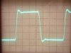
5. A 10 kHz square wave display is provided for the modified amplifier, shown at a 1 watt power level, across a normal 8 ohm non-inductive resistive load. It changes very little when a speaker replaces the resistive load used for testing. A comparison with the 10 kHz display of the original design generated under the same conditions as provided in post #45 will show the obvious improvement in frequency response in the modified amplifier. In spite of the improved response, the waveform is still well damped, settling very quickly after the initial rise of the leading edge, with a smooth wave top extending to the end of the cycle. This indicates a very high level of stability.
I will attempt to get a schematic drawn up of the revised design, and posted here asap. But for now, a bit of a break for family Christmas season events, and then the last elements of the redesign effort will be addressed.
Dave
Attachments

s-petersen
Scott
Nice transformation!, I always enjoy reading of your adventures.
Rock -- Thanks so much for the kind words, and it's a great question you ask. In short, no, I don't believe tube life will be compromised at all -- and I don't say that with a private hope and a prayer.
At the heart of my answer lies the very reason for the effort in the first place: The re-purposing of a unit that was originally designed for continuous, sustained operation at high power output levels as a sound distribution amplifier, into a much higher quality sound reproduction amplifier with the same power output capability, but with comparatively very light intermittent use. Based on this alone, I would suggest that the two tubes used in this modification, will still well outlast the four used in the original design, based on intended service.
To your point however, in an absolute analysis, there is no doubt that four tubes doing the work of two will last longer, with all else being equal. However, when you consider the expense of the additional tubes and the support circuitry to properly balance four tubes (for both AC and DC properties) in a manner similar to the way that two have been done to achieve the performance level attained, coupled with the fact that tube life would be the only real advantage to be had, and comparing all of this then to the completely new and different intended use and service model over that of the original design, then the use of four tubes per amplifier pushes that need well, well past the point of diminished returns.
Consider too that it is anticipated that once the output stage operates under the control of EFB, individual output tube dissipation levels under quiescent conditions should only be around 26 watts. For a tube that is rated for 35 watts dissipation, this means each tube will be operating at just under 75% of their rated dissipation level, which is a very conservative operating point for tubes as used in the new intended service model.
Finally, understand too that the amplifier so modified is hardly so reduced in strength that it can barely attain the original power output level, or only do so for short bursts at a time. In fact, quite the contrary is true. With such a major redesign of a unit, I always consider possible abuse and long term high levels of operation as likely possibilities. To that point, I have had the modified amplifier develop a sustained 100 watt RMS power output level for over 1/2 hour, with no signs of distress in the output tubes at all. I shut it down after about 45 minutes, seeing little advantage to continue with the test. After the test, the two mule test tubes were again tested in my power output tube tester, with no change in power output capability over that of their original test condition.
I should have addressed this question in more detail earlier, but for the reasons given, am quite confident that the tubes in the new configuration will have every bit as much life expectancy -- and most probably much more -- that those of the original configuration and service.
Dave
At the heart of my answer lies the very reason for the effort in the first place: The re-purposing of a unit that was originally designed for continuous, sustained operation at high power output levels as a sound distribution amplifier, into a much higher quality sound reproduction amplifier with the same power output capability, but with comparatively very light intermittent use. Based on this alone, I would suggest that the two tubes used in this modification, will still well outlast the four used in the original design, based on intended service.
To your point however, in an absolute analysis, there is no doubt that four tubes doing the work of two will last longer, with all else being equal. However, when you consider the expense of the additional tubes and the support circuitry to properly balance four tubes (for both AC and DC properties) in a manner similar to the way that two have been done to achieve the performance level attained, coupled with the fact that tube life would be the only real advantage to be had, and comparing all of this then to the completely new and different intended use and service model over that of the original design, then the use of four tubes per amplifier pushes that need well, well past the point of diminished returns.
Consider too that it is anticipated that once the output stage operates under the control of EFB, individual output tube dissipation levels under quiescent conditions should only be around 26 watts. For a tube that is rated for 35 watts dissipation, this means each tube will be operating at just under 75% of their rated dissipation level, which is a very conservative operating point for tubes as used in the new intended service model.
Finally, understand too that the amplifier so modified is hardly so reduced in strength that it can barely attain the original power output level, or only do so for short bursts at a time. In fact, quite the contrary is true. With such a major redesign of a unit, I always consider possible abuse and long term high levels of operation as likely possibilities. To that point, I have had the modified amplifier develop a sustained 100 watt RMS power output level for over 1/2 hour, with no signs of distress in the output tubes at all. I shut it down after about 45 minutes, seeing little advantage to continue with the test. After the test, the two mule test tubes were again tested in my power output tube tester, with no change in power output capability over that of their original test condition.
I should have addressed this question in more detail earlier, but for the reasons given, am quite confident that the tubes in the new configuration will have every bit as much life expectancy -- and most probably much more -- that those of the original configuration and service.
Dave