• The move to the new server is done. There are some software and database maintenance updates in process. This has us passing the hat around to help out. We appreciate any donations. Seriously, even a dollar helps. The payment page may be found here - https://www.audiokarma.org/support.html

The Mighty Bogen MO-200A

Nice char marks on the chassis. I love opening things and seeing obvious carnage inside, occasionally with it totally unrepaired. At least when I find it unrepaired, I know why it was taken out of service :) One of my 100a's has some char marks around the balance pot. Its almost like you cant mix 6L6G tubes with 8417's at nearly double the rated voltage of the 6L6G and expect it to function properly.


I like the idea of the separate bias transformer. The stock system always seemed a bit sketchy to me in execution. I guess it works well enough for the original design though, so you can't fault them too much for it.
 
Jaz -- That's the thing. Just as with the MO-200 I'm working on, it's the AF amplifier stage that is being over driven BEFORE the output tubes are being over driven. Therefore, the output tubes themselves were not clipping, but were being sent an over driven signal before they themselves were reaching an over driven state.

To specifically answer your question however, yes, as long as the AF amplifier stage was not being over driven, then everything was peachy without the pulsating output -- except that the threshold between clean power and pulsating overloaded power happens very quickly, and was happening below rated power output, meaning that effectively, all the available power the unit was capable of could not be used.

Dave

Thanks for the clarification - I re-read your post and sure enough it said the driver was over-driven not the output tubes, duh! Time to get new glasses...
 
Sonic Comparison

Christmas Eve means lots of great music -- which gave me a chance to finally listen to the Bogen for the first time, and now, operating in stereo mode for the first time as well. For the test, the one modified amplifier of the MO-200 was designated as the Left Channel, while the other original amplifier was designated as the Right. The stock (Right) channel was converted to exactly follow the schematic of the MO-100 (requiring only a change to the NFB loop and cathode resistor of the AF Amplifier stage), complete with it's four output tube operation and bias supply (the latter being identical to that of the original MO-200). The modified (Left) channel represented the schematic I've previously presented, and operated from the new bias supply, but without the benefit of EFB just yet. Both channels had their available controls adjusted for optimum operation.

The now stereo MO-200 was driven by a Scott LC-21 preamp, with my trusty Denon DCD-1520 providing the source signal. Much of the material played was Mannheim, but there was also a healthy dose of vocal material as well. The Bogen was driving my 8 Ohm Cornwalls, with the speakers attached to the OPT taps in each channel as designated on the modified schematic for 7.6 Ohm operation. An available 200 watts RMS and a pair of Klipsch Cornwalls places this getup in earth mover territory!

Because the modified channel has the same input impedance and sensitivity characteristics as the original channel, no padding was necessary for either channel to match their output levels for a well balanced and focused sound stage. The Scott allowed for listening (in part) in Stereo, Mono, Left Only, and Right Only modes to really listen for differences in presentation between the two channels.

From a sonic assessment standpoint, Double Blind A/B testing is the only way to determine if progress is really being made with a design, as emotions and psychological factors can so very easily cloud honest assessments if any significant amount of time elapses between one test to the next. But since it takes at least two people to conduct double blind testing (one to control the test, and one to assess), the approach I've used here is about the next best thing you can do: Modify only one channel at a time, and regularly compare the results to the other unmodified channel as the modification effort progresses. I used that approach with the recent re-engineering of a Fisher X-1000 project as well, and the results it produces can be brutally honest: Many times, your improvements are not all that you thought they were going to be -- or, the original design just wasn't as bad sonically as you thought it was. It truly allows you to showcase the difference any modification makes by allowing for instantaneous comparisons, which then allows you to judge for yourself the worthiness of any proposed hotshot modification -- be it mine, or anybody else's!

In this case however, the differences were pretty easy to spot. While the original (MO-100) channel sounded "good" when playing for long periods by itself, instant comparisons to the modified channel showed rather immediate differences: Compared to the modified channel, the original channel had a forward midrange, and reduced (thinner) bass response. It also lacked a level of HF detail, that by comparison came off as present, but dull. And there was one other element as well. The original channel produced a comparatively lifeless sound to that of the modified channel.

Against all of this, the modified channel had very solid, extended bass, balanced midrange (no longer forward), and more detail in HF production. It also had a live, dynamic sound that the original channel was missing.

None of this was a big surprise, really. The lifeless sound is a direct result of the original channel operating the output tubes at such low quiescent current levels, the thin bass response due to very short time constants in the coupling circuits between the phase inverter and output stages in the original design, while the original NFB network produced a notably rolled off HF response. The results clearly indicated that moving forward with the modifications were worthwhile, beyond that of simply splitting the individual amplifiers apart to effect stereo operation.

Since all of these listening tests were done at relatively low power levels (let's face it, Cornwalls don't need much power to get loud), I augmented the listening tests with high power tests as well. I mean really, who in their right mind would connect 100 watts RMS per channel up to Cornwalls? As it was, I used duplicate ground connections between the preamp and Bogen as a safeguard to make sure no 100 watt loss of ground bursts hit the speakers -- or my ears!

For this test, the best I could do was to use my load array set up for stereo 100 watt 16 Ohm loads connected to each amplifier appropriately, and then power the Cornwalls through an appropriate series resistor to maintain a normal sound level. My average and peak indicating stereo power output indicator was then connected across the output of each channel as well.

This type of operation is not exactly the same for the amplifier as a loudspeaker connected and producing 100 watts of power, nor to the speaker either with a now very reduced damping factor. But it is close enough to get an idea of high power performance characteristics at elevated power levels.

At 50 watts of average power output (APO) per channel, both channels treated this power level as a walk in the park. By 75 watts APO, the modified channel was still very clear, while the original channel was starting to take on a somewhat strained element to its sound. At about 80 watts APO, the modified channel was still quite clear, while the original channel was starting to produce that pumping, pulsating effect, that I described two posts earlier. At about 85 watts APO, things were still very good in the modified channel, but the original (MO-100) channel had completely broken down to a wild pulsating/pumping effect, exactly as I had heard in all those MX-60 amplifiers, so long ago. At 100 watts APO, the modified channel completely retained its composure, but of course clipping could now be heard on peaks, as peak power was now indicating over 215 watts in the modified channel! At this point however, the original Bogen channel had completely lost its composure, producing about 165 watts peak power output (best guess with all the pulsating going on).

So, it was an interesting test. I just thought I'd pass all the results along while they were still fresh in my mind. Pics include:

1. The new bias supply is completely installed now, providing bias for the modified channel. The whole power supply area almost looks vacant now compared to that when received (post #1)

2. But to have the original channel operate at its intended bias level, the original bias supply was carefully reconstructed using my best air connection techniques, and connected umbilical style through some cooling holes to provide bias for the channel now configured as an MO-100.

3. All connected up in the listening room, ready for a day's worth of listening in stereo.

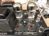
4. Here, the bias umbilical can clearly be seen. The front driver tube and four front output tubes represent the MO-100 channel, while the rear driver tube and two output tubes represent the modified channel.

5. Don't be fooled. Those two rear output tubes blew right past the four in front of them. Here, the rear two tubes are producing a surprisingly clear APO of 100 watts RMS, while the front four tubes are pulsing the sound in and out at about a very distorted 85 watts RMS.

On a side note, the power transformer in this puppy handled all of this day's activities in stride as one cool customer: It only became moderately warm to the touch!

Some time off for now.

Merry Christmas everyone!

Dave

 

Attachments

  • Bogen MO-200 Sonic Testing 001.jpg
    Bogen MO-200 Sonic Testing 001.jpg
    109.2 KB · Views: 95
  • Bogen MO-200 Sonic Testing 003.jpg
    Bogen MO-200 Sonic Testing 003.jpg
    97.3 KB · Views: 102
  • Bogen MO-200 Sonic Testing 005.jpg
    Bogen MO-200 Sonic Testing 005.jpg
    102.4 KB · Views: 105
  • Bogen MO-200 Sonic Testing 006.jpg
    Bogen MO-200 Sonic Testing 006.jpg
    83.6 KB · Views: 96
  • Bogen MO-200 Sonic Testing 004.jpg
    Bogen MO-200 Sonic Testing 004.jpg
    51.9 KB · Views: 109
This is a really interesting read, Dave. I am very much looking forward to the conclusion of all this... making me want to sideline everything else and drag out a couple of Bogen M120s and apply some of these ideas.

Merry Christmas Dave!
 
Interesting, and its nice to know for sure that the numbers don't lie. I'm all the more motivated to do something with my 100a's, though it also makes me want to buy some nice inefficient speakers to drive with them :)
 
Quick Detour

Before proceeding with the development of EFB for the output stage, there have been a number of requests concerning the use of alternate output tubes that can be used with this amplifier. Since the new bias supply was installed and could develop the necessary bias for all the traditional tube choices, I thought I'd take a quick detour to see how well each could perform.

EL34 -- Bricktops's modification used a quad of these tubes in each channel along with the Blumlein cathode balancing circuit to produce a maximum power output of about 65 watts per channel.

The Blumlein circuit however is best suited for Class A output stages, as it places significant resistance in the cathode circuit to make the balancing scheme work. With a steady current draw from the output stage, then the extra resistance is of little concern other than for the heat produced, and loss of B+ voltage it consumes. If these are accounted for, then no harm, no foul.

For Class AB designs however, the added resistance of the Blumlein circuit really works against producing maximum power output and minimum distortion levels, as even with the cathodes well bypassed, the bypass caps can do nothing to address the increased average current draw that Class AB designs always exhibit with elevated power levels. As a result, Bricktop's modification would not be a good indicator for what two EL34's could produce with the current modification effort.

Two sets of EL34s were then tried: A good used set of RCA labeled tubes of authentic Mullard tooling, and a pair of new European tubes of some decent, labeled, boxed, and sold under the Hoges name (whoever that is). These were purchased as new production stock in Europe some 15 or more years ago, and look like the classic "slimmie" versions of these tubes. While there is 700+ volts available in this amplifier under quiescent conditions, the screen voltage is only on the order of about 355 volts with no signal. These voltage levels should be easily handled by even the low end of current day production tubes, so these tubes were good candidates for the test.

The Hoges required more bias voltage than is typically required by EL34 tubes, but none the less, could be biased at 38 ma (total) each, for a dissipation level of 25 watts per tube. A pair of these tubes could produce 85 watts RMS, with reasonable distortion (the NFB circuit was not altered for these tests), but also displayed significant screen heating at this power level.

A quick check was then made to see of the screen heating was a tube issue or circuit issue, so the two RCA/Mullards were then installed, and biased to the same operating point. These tubes produced 95 watts RMS, but also displayed screen heating as well. The 8417 tubes in two tube operation showed no screen color at any level of power output.

Therefore, while the EL34 is the easiest tube to drive of the more traditional "big" output tubes, it is also the most fragile. Using four such tubes would only aggravate the screen heating issue, and reduce screen regulation over that of two tube operation, which would increase distortion.

The only real answer then is to reduce the screen voltage, which -- to do so properly -- would require some element of regulation for the screen circuit, and further reduce circuit efficiency. In any event, to maintain the original, true 100 watt rating of this amplifier per channel, four EL34 tubes would be required per channel, with EFB screen regulation (or otherwise) required to maintain the screens within their rated dissipation levels. Use of the EL34 then could only be recommended with appropriate (and significant) screen circuit alterations.

KT88 -- Two well used but authentic Genalex tubes were installed. These tubes had serious evaporation of the getter flash evident, but still produced 81% of average new power output for these tube types in my power output tube tester. In terms of an English scale (BAD-?-GOOD), this is just into the very bottom of the good range. The life expectancy of these tubes is legendary, and these two tubes are working proof of that fact.

These two tubes easily produced 95 watts RMS, even in their compromised state, so solidly good tubes should easily produce at least 100 watts output. As a test of this fact, two very good (but used) 6550A tubes of GE tooling were also tried, producing 115 watts of power output in two tube operation.

Both the KT88 and 6550A tubes were biased to a quiescent current of 40 ma, for a dissipation level of just over 27 watts. To adequately drive these tubes, the phase inverter B+ level was raised significantly to produce the added low distortion drive capability necessary for these tubes from the existing phase inverter circuit.

Based on these tests then, the 8417 is by far and away the best tube for the basic topology used in this amplifier: It can easily be driven by the existing phase inverter circuit, and being a beam power tube, its screen grids are well protected, showing no color at any sustained level of power output.

Next would the the KT88/6550 class of tubes, as they are equally durable screen grid wise as the 8417 is, and are capable of at least as much undistorted power output as the 8417 is. To use these tubes to best advantage while keeping the same basic topology, would require converting the 7247 to (typically) a 6AN8 type tube, and also require elevating the driver stage B+ as well.

Finally, for two or four output tube formats, EL34 class tubes could easily be driven by the existing driver circuit, but would require significant work to support the screen grid circuit, with ultimately four tubes being required to maintain the 100 watt power rating. Four tubes then brings in the added complexity for biasing and balancing each tube (as well as for AC balancing as well), and so would be the last tube of choice for this amplifier.

These modifications could certainly be made. But they really start moving the design away from the topology of the original design, which greatly increases the complexity of any proposed modification. No doubt, very good performance could be achieved from this work, but there is no expectation that is would be any better than that produced by two tube 8417 or 6550 operation.

Going into this project, I was hopeful that two tube operation of the EL34 would fare better than it did, since it could be driven by the existing driver circuity. With screen voltages approaching just 300 volts under full power conditions, I was hopeful that the load impedance would be low enough to keep the screens cool under full power conditions, but such is not the case. Reducing their voltage then only further reduces power output, and absolutely necessitating the need for four tubes to develop 100 watts of power.

Pics just show the tubes used for the tests:

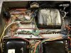
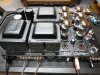
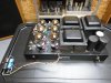
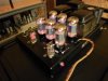
1. These new slimmies produced 85 watts RMS, with significant screen heating.

2. These used, but solidly good RCA/Mullards produced 95 watts RMS, but also had unacceptable screen heating.

3. These well used Genalex KT88s also produced 95 watts RMS, and did so with no screen heating at all.

4. These used, but solidly good RCA/GE 6550As had no screen heating, and had no problem producing 115 watts RMS -- besting the best power output recorded by the very strong 8417 tubes used throughout testing to date.

Still trying to get some time off!

Dave
 

Attachments

  • Bogen MO-200 Alternate Power Tube Tests 002.jpg
    Bogen MO-200 Alternate Power Tube Tests 002.jpg
    82.9 KB · Views: 63
  • Bogen MO-200 Alternate Power Tube Tests 003.jpg
    Bogen MO-200 Alternate Power Tube Tests 003.jpg
    91.3 KB · Views: 57
  • Bogen MO-200 Alternate Power Tube Tests 001.jpg
    Bogen MO-200 Alternate Power Tube Tests 001.jpg
    92 KB · Views: 63
  • Bogen MO-200 Alternate Power Tube Tests 004.jpg
    Bogen MO-200 Alternate Power Tube Tests 004.jpg
    97.5 KB · Views: 70
Screen heating. It appears to be a subjective measurement, so, in my own experiments, how do I know when I have an overheated screen?
 
How far apart would you say the 8417 and the 6550/KT88 are? For myself, I'm looking at costs. I could come up with a quad of new production 6550 types for under 150, where 4 NOS 8417's are more like 350. Used ones are cheaper, but those can be questionable and even so the availability of the 8417 is not getting better.

With something like a 6AN8, I take it the primary reason is the pentode section for more voltage gain, and the increased B+ is on the triode to allow for a larger voltage swing to drive the output tubes?
 
Rust -- I certainly treated it as a subjective measurement for sure. But each tube also has scientific data available of course stating maximum ratings for screen dissipation, with actual dissipation both being able to be estimated from graphic data, and measured as well. The subjective element came in because these tests were simply quick and dirty tests to check for an end result.

Screen heating is one of the biggest concerns regarding catastrophic failure, and/or long term retention of characteristics. A screen grid that shows any significant color under any mode of operation is subject to warpage which can result in a permanent change in its physical shape. This -- at the very least -- can result in a permanent change its performance characteristics, or in worst case examples, cause the grid to come into contact with other elements -- most notably, the control grid -- with the obvious end result produced.

The only tube I had any real concerns about regarding this issue going into these simple tests was with the EL34. As a true pentode, its screen grid does not share the same protection afforded this same element in a beam power tube, making the screen grid in the EL34 more susceptible to heating under high current conditions. Other "power pentode" tubes are susceptible to this same concern as well (i.e. 6BQ5 and 7591 class tubes for example), so screen heating is one of the very first concerns I check for when working with these tube types.

For example, in my documentation of adding EFB(tm) to a later model Fisher 400 receiver over on the Fisher forum, this was a major concern of the original design in that unit. This resulted in the EFB circuits not only being used to add EFB action for control of output stage operation, but also used to alter the basic output stage operating point to operate the tubes in a much safer manner as well. This effort resulted in the same level of power output being produced, with much lower distortion, greatly extended tube life, and all with no glow from the screen grids even under extreme overload (worst case) conditions.

To answer your question directly most directly then, the safest way to know that a screen grid is operating safely is to make sure its actual dissipation levels do not exceed published ratings for it under any mode of operation. But from a practical standpoint, any significant glow from a screen grid under any conditions of use cannot bode well for the future of the tube!

Dave
 
Gadget -- You nailed it. The 6550 is ultimately capable of the best performance from this unit. And, from an implementation standpoint, it would also be the easiest tube to convert to as well, since the circuits to properly control the screen operation of EL34 tubes would require heat sunk SS devices, which many folks simply don't want to mess with. In converting to 6550 operation, the screen control circuits would not be required, while converting a one tube driver circuit to an alternate one tube circuit with altered B+ values is something many would tackle.

Dave
 
Re: measuring screen dissipation, I can easily check this by measuring the voltage across any screen stopper resistors and calculating the current, correct?
 
In rereading my last post, I did not mean to pass over the performance of the 8417. While the 6550 can best that of the 8417, we're hardly talking about significant differences here. The 8417 has in fact proven to be a rather formidable tube indeed in this application, especially considering the performance it delivers from how little it requires to deliver it. For those with 8417 tubes available to them then, a switch to 6550 tubes just for the sake of the switch would be a silly exercise. But where starting from scratch tube wise (as in Gadget's case), or concerns of ultimate availability are an issue, then the 6550 tube is the clear choice for conversion for the unit to operate with.

Dave

Again, this is based on trying to maintain as much of the original basic topology as possible.
 
If a person preferred the ability to run 6550's with a new driver circuit as well as 8417's (which seem to be quite happy with the relatively stock circuit) due to the more available 6550/KT88, could a means for switching be added. Such as a switch and additional circuitry, and/or would the chassis even allow for it in stock form? ie: enough tube sockets, enough underchassis room for additional circuitry, switches, etc? Seems like that would be a rather extravagant change for not much reward.

Also, if one was kept in it's 200 watt mono operation with your various upgrades and modifications, would you expect similar performance but at double the output power, or would that introduce some other anticipated problems? Who needs 200 watt tube amps anyway?

Dave, I see you were typing while I was!
 
Last edited:
Rust -- You've got it. In checking actual dissipation, calculate the current, and then the dissipation -- and do so under various modes of operation to ensure the ratings are maintained under all conceivable conditions of use.

Note that some tubes allow for an increased rating under "peak levels of speech and music signals" -- as opposed to the standard rating which would apply to sinusoidal testing. The thought here is that the increased rating is allowed for brief overload periods (relative to the standard published value) that these types of signals can produce, versus the steady state dissipation that the repetitive nature of sinusoidal signals produce.

Dave

Dave
 
rpampt -- the unit could in fact be modified so as to operate with either 8417 tubes or 6550 tubes. It just needs to be built to accommodate the tube with the highest drive requirements, and then modified as appropriate from there to accept the tube with lower drive needs when needed.

For example, I have a rather decent mule power amp that I use for various utility needs, that is designed to run either 6V6 tubes, or with socket adapters, 6BQ5 tubes. From an electrical standpoint, changing between these two tubes types is nearly as big a change as converting from 8417 tube to 6550 tubes in the Bogen -- this because in both cases, one tube type represents about twice the Gm of the other tube.

Once the circuit can accommodate the tube with the greatest drive needs, then all that is needed to convert to the tube with less drive is to adjust the bias, and adjust the NFB circuits so that the proper parameters are maintained with both tubes. In fact, a simple switch does accomplish this in the utility amp I mentioned. The only real world significance between the changes (besides that of the tubes themselves) is that when the tube with higher sensitivity is used, the unit itself will in fact display higher sensitivity as well. Of course, this could also be accounted for if need be.

In the case of the Bogen, it would require developing a new driver circuit to handle the 6550, which could then be easily "switched" to accommodate 8417 tubes when/if desired.

It's all just an engineering exercise. Once that goal is clearly defined, then the work can be done to achieve the stated goals.

Dave
 
There are physically enough sockets on the Bogen chassis. I suppose if you really wanted to, you could wire up two that are essentially in parallel as far as feed and output go. One could be the stock 7247 to drive the 8417 tubes, and the other could be a pentode/triode of your pick to drive something else. You could of course only run one of these tubes at a time, but I suppose its an option.

A possibly easier option, convert the driver to a pentode/triode and simply triode-strap the pentode section for reduced gain via a switch if you wanted to run 8417 tubes. That might be less messy than having 2 different input tube sockets that are "live" at the same time.
 
Hiya,

I guess another benefit to converting to the KT88/6550 type is that you would be able to potentially roll in the KT90-KT150 lineup of tubes (Prob already stated in this thread somewhere)

Dave thanks again for this. My MO100's were saved from the dreaded shuffle to someone else. They are staying put!!!

Frannie
 
The "dreaded shuffle" -- I love it! Frannie, you have a way with words!

If there's enough interest and rpampt is willing to allow the project to get sidetracked, then now would be an opportune time to look at developing a 6550 conversion for the Bogen as well:

1. All that is really left to develop with the existing modification project is the EFB circuits for the output stage.

2. The new bias supply could easily handle the normal bias supply duties for 6550 tubes, even with the loss created through the new bias/balance controls installed (although it would need to be redone again to handle 6550s controlled by EFB).

3. Since the need for the one original Bogen channel now remaining (now an MO-100) is really finished with the sonic comparison tests all done, that channel could be converted to two tube 6550 operation, maintaining as much of the original topology as possible by using a 6AN8 driver tube. This would then allow direct comparison of the now modified 8417 channel, to a 6550 conversion channel, which might be interesting.

The only real obstacle to this approach would be to develop some sort of delay circuit for applying B+ power to the 6AN8. Using the half doubler supply point as is now used for the existing driver circuit would almost certainly not provide an adequate amount of B+ to the driver tube under full power conditions to properly drive 6550 tubes with a low distortion drive signal. That would mean that power would need to come from the main B+ source.

For those familiar with the circuit of the Dynaco MK VI, they had a similar problem in developing that amplifier, solving it with a time delay relay tube. The delay is needed because with a SS B+ power supply, the high amount of B+ available at turn on well overshoots the maximum safe plate and screen voltages of 6AN8 type tubes before they warm up -- with this case being much worse than encountered in the MK VI, since the initial main B+ value at turn on in this unit is ~ 750 vdc.

No doubt that either a simple shunt circuit could be developed using a 555 timer, or, a slow warming damper tube could be placed in series with the driver B+ lead to allow the driver to warm before B+ is applied by the damper tube (or full B+ is applied by the timer circuit). Frankly, I like the damper tube approach, best.

Comments welcomed.

Dave
 
Love this thread. I wonder if it might reflect the hand drawn paper / napkins, phone/snail mail discussions had by David Hafler and his tube engineers during their time developing the Mk II/III/IV/VI, and deciding what choices they had to work with.

Could you imagine the discussions they had? Of course back then, the issue of quality of tubes was not a problem, but reliability, ease of construction, and the price point which their products had to sell at obviously played a role. And I think the one point that they had is they were developing their output transformers and deciding what to do with them. We don't have that luxury here with the already defined Bogen output. So a lot of choices are woven around what is already existent and working with that.
 
Could something a bit more crude be done using a zener diode in a voltage divider rig to "cap" the max B+ going to the 6AN8 to some safe value? If you wanted it out of the circuit, it could be set to some voltage higher than would normally be seen by the tube, and serve only as a limiter to keep it from frying on startup.
 
Back
Top Bottom