Alternate Design
Some additional tests were run to determine just how significant an improvement could be had by converting the output stage to 6550 operation. As discussed earlier, this requires a change in the driver circuitry for maximum performance to be achieved.
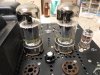
For this test, I broke out a pair a brand new Sylvania 6550 tubes, which are quite distinguishable by their somewhat unique shape for these tube types. Also as before, I upped the juice to the existing driver circuit to supply the additional drive -- a move that along with removing the NFB connection, allowed for the tests to be made, but would not be practical for any real world design.
These tubes produced the expected bump in power output -- easily producing a sustained 120.0 watts RMS with zero signs of output tube distress -- but also delivered one other hoped for result as well.
Early comments on the performance of the original Bogen design included the observation of the quite poor screen voltage regulation, and the significant contribution to the distortion this causes in pentode amplifiers. However, the installation of EFB can easily gain control over the havoc this creates. When installed, the low distortion operating point will be maintained regardless of screen voltage regulation, with simulated EFB testing indicating a 1 kHz THD of about .22% at 100 watts RMS from the modified design. This level of performance represents a significant improvement from where the original performance started (1.65% at 200 watts, both channels still in parallel operation), representing nearly an 8 fold drop in distortion, and all with no increase in NFB to achieve it. Complementing this, the improved frequency response of the modified design (to 50 kHz +0/-1db), corrected input stage overload issue, the ability to properly bias and balance the output stage, and the revised OPT load connections all make for a very much improved Bogen, as re-purposed for home stereo sound reproduction use -- and all with using only two output tubes per channel, yet still maintaining the same level of total power output. For those wishing then to optimize the stock performance of their 8417 based MO-100/200 amplifiers, this would be a very good way to go.
But conversion to 6550 operation may be appealing to others. While this tube has significant drive issues as compared to the 8417, it is also a more efficient tube with respect to the production of power: Under conditions of maximum current flow -- as compared to its 8417 or EL34 brethren -- the 6550 is simply able to channel more of its total current flow to the plate, with less current lost through the screen circuit. This not only maximizes power output, but also significantly improves screen voltage regulation from practical screen grid power sources -- so much so in the Bogen, that EFB may not be required with 6550s to match the distortion performance produced by 8417 tubes under EFB control. Further testing will tell that tale. Finally of course, less power consumed by the screen circuit means less screen dissipation as well. So potentially then, 6550 tubes are (will):
1. Cheaper, more available, and in current production.
2. Capable of producing the most power output. How current production 6550 tubes stack up against good NOS 8417 tubes is unknown. This could be a factor in tube choice as well.
3. Capable of producing the lowest distortion -- or -- may not require EFB to achieve that produced by 8417s, or at least a very acceptably low distortion.
4. Require a new driver circuit to properly implement their installation.
With this last thought, some attention was then turned to developing a revised driver circuit, keeping it as simple as possible in keeping with the original topology, yet having it fully capable of providing a low distortion drive signal, capable of properly driving push-pull 6550 tubes to full power output in the Bogen environment.
Tests had previously shown that an 85 volt peak-to-peak signal would be required (42.5 volts peak per tube), and this to be developed across a 47K output tube grid return resistor -- this to keep this value in line with the 50K maximum Grid #1 DC resistance allowed for 6550 tubes when operated in fixed bias operation.
Further testing showed that the triode section of a 6AN8 tube, when properly biased, could develop as much as 100 volts peak to peak (50 volts peak per tube) with low distortion, across the required grid return resistor value for 6550 tubes. This required a B+ voltage of 400 vdc to the inverter stage, setting the minimum allowable B+ to this stage under full power output conditions.
With R/C coupling used between the pentode and triode sections of this tube, it avoids the pitfalls normally associated with this kind of gain stage/inverter configuration, by not allowing the plate voltage of the pentode section to have any effect on the operation of the inverter stage. Normally, slight variations in the mechanical construction of the pentode tube section can cause wild variations in screen voltages produced with typical circuits, which in turn affects the pentode's plate voltage, which in turn affects the inverter stage if direct coupling is used. By using R/C coupling, these concerns are avoided, and performance then becomes quite consistent from tube to tube.
The pentode gain stage section can be configured to provide a gain of over 300, which would produce a working input sensitivity requirement of under 1 volt (estimated at about .65 volt) after the application of the original 17 db of NFB. Or, it can be configured for a gain of something over 100, which would return a similar input sensitivity as that of the original Bogen design (estimated at about 1.85 vac) once feedback is applied. Comments appreciated on which sensitivity is more desirable.
In any event, this work has allowed building blocks to form, allowing for an alternate design using 6550 tubes and a 6AN8 tube for the driver position. These tubes are more readily available, with this design also providing significant improvement over that of the original Bogen offering, when using this unit for home stereo use.
A few quick pics:
1. These bad boys developed the most power output of all in the Bogen chassis, reliably producing a sustained 120 watts RMS at 1 kHz before the onset of clipping. Of course, this power will fall somewhat when both channels are driven, but power will still ably exceed the original 100 watt specification.
2. Using more traditional circuit development methods (i.e. a mess), the new driver circuit is undergoing testing and measurement.
3. With each division calibrated for 20 volts peak, here is a very clean 50 volt peak 20 Hz sine wave presented from each side of the inverter, after a coupling cap into a 47K following stage load. This is significant, as the low frequency/low distortion output capability of many such driver circuits AFTER the coupling cap can actually fall below the needs of the output stage to reliably produce full power output. This driver circuit is capable of driving 6550 tubes, and therefore any other typical output tube, to full power capability across the full audio spectrum with low distortion, in most typical pentode output stage designs.
All that would be left then would be to develop an appropriate B+ tap for the new driver stage to operate from, and of course the NFB network and stability circuits once the driver is installed. As always, all comments welcomed!
Dave



 Have at it Dave in whatever manner you see fit, if people have interest. Everything is reversable, right?:yes: