

You are using an out of date browser. It may not display this or other websites correctly.
You should upgrade or use an alternative browser.
You should upgrade or use an alternative browser.
The Mighty Bogen MO-200A
- Thread starter dcgillespie
- Start date


I thought Dynaco was into the 7199 or whatever it was thats NLA? Or is that just what the ST-70 used? I don't know Dynaco very well at all. The only amps I've personally had with pentode/triode tubes were Stromberg-Carlsons, and they rock the 6U8, which is another one of those silly cheap tubes.

I am with PIO1980, sounds like the sale for the 6an8 has been made.
If it were me, with my limited abilities trying to clone your work/mods etc, in another 100 or 200, I would certainly be more apt to take it on the simpler the process would be. Especially since it sounds there is no lack of performance in going that route and also balancing it against the possible additional costs of time and parts involved for a total driver section redesign. Folks here that have alternate ideas (and it sounds like there are great ones) who skill levels are much higher would be more likely to take on a more difficult or more involved design, especially if it might save some $$$ on replacement tubes over time. But like you Dave, I think that if it just gets too far away from what it was originally, folks are less likely to even tackle the project. Just my 2 cents. You can experiment all you like, but for me, in this case, it appears that the 6an8 is the way to go. But I've got to say, it certainly is educational and greatly entertaining hearing all the ideas and applications that are discussed. Thanks all!
If it were me, with my limited abilities trying to clone your work/mods etc, in another 100 or 200, I would certainly be more apt to take it on the simpler the process would be. Especially since it sounds there is no lack of performance in going that route and also balancing it against the possible additional costs of time and parts involved for a total driver section redesign. Folks here that have alternate ideas (and it sounds like there are great ones) who skill levels are much higher would be more likely to take on a more difficult or more involved design, especially if it might save some $$$ on replacement tubes over time. But like you Dave, I think that if it just gets too far away from what it was originally, folks are less likely to even tackle the project. Just my 2 cents. You can experiment all you like, but for me, in this case, it appears that the 6an8 is the way to go. But I've got to say, it certainly is educational and greatly entertaining hearing all the ideas and applications that are discussed. Thanks all!
Thanks for all the interesting ideas. All the tubes mentioned certainly have their attributes and possibilities in the appropriate application, but some hard facts will help to bring some reality to this matter rather quickly.
With 6550 tubes and the current driver topology, a standard 1 volt input sensitivity will require the AF amplifier input stage to provide a gain of about 235, assuming that 17 db of NFB will be maintained as used in the original design. This quickly rules out any triode ever produced on this planet. Even if the original (basically) 2.0 volt input sensitivity is accepted, then the AF stage still has to supply a gain of 118, which no single triode is going to supply with any stability. The only triode that would have a prayer of getting close to this much gain would be a 12AX7 stage employing a CCS plate load element, and positive feedback to further eek out whatever gain hadn't been achieved before instability set in. That is simply not a good row to hoe.
Now if we completely abandon the original basic drive stage topology altogether, then a Mullard configured driver stage becomes the next best bet from a standpoint of simplicity. In this scenario, the AF amplifier stage only needs a working gain of about 35 to maintain a 1 volt input sensitivity with 17 DB of NFB, and assuming a cathode coupled inverter stage gain (to either output) of ~ 6 (typical of say, a 12BH7). But this configuration also needs either a CCS in the long tail of the inverter, or about a stout -80 volt source to supply the inverter's tail resistor if enough current is to flow in this stage to develop the needed drive at each output tube grid across the 47K grid return resistor that 6550 tubes require in fixed bias applications.
Finally, since the unit now uses 2 output tubes per channel, another possibility is to use the two remaining octal sockets in each channel to install a capable Williamson front end, using 6SN7s. This type of front end would require the most tubes of course, and would likely be the most complex. But it would not require any CCSs, could operate solely from the bottom half of the doubler, could still achieve about a 1 volt input sensitivity after feedback, and could also drive the 6550s right out of their sockets.
Against all of this however, the 6AN8 driver DOES do the job very well with a 20% reserve drive capability, and offers the greatest simplicity and economy, with no compromise in performance. If this project is to maintain even one ounce of its MO-100/200 heritage, then its got to be fairly simple, or these things are either going to end up with a lot of rust, or hopelessly lost in the dreaded shuffle that Frannie so aptly warned of.
Also of course are rpampt's thoughts on all of this: After all, it is his amp!
Dave

I meant to mention to Nerd that the 6W6 is in fact a wonderful tube, and has a long heritage behind it as well: Other than for its 6.3 volt heater, it is identical in every way to the famous 50L6, which is the 50 volt version used as the power output tube in countless millions of AC/DC All American Five table radios produced throughout the 40s and 50s. Its a relatively low voltage tube that manages to produce a respectable amount of power from power supplies of only 125 volts or so, and was produced in such quantity as to still be readily available today, although its cost is climbing..........
Dave
Dave
At this point, I think the 6AN8 driver really is the way to go. Projects of this magnitude are always in danger of getting bogged down due to indecision, or lack of forward progress. Sometimes, they can get so grandiose and complex, that the resulting product actually ends up returning less performance than that of the original design. Good planning and engineering can usually prevent that, while adhering to the kiss principle of keeping it simple is always the best way to keep things moving. In this case, the 6AN8 driver is quite capable of allowing 6550s to produce all the performance they are capable of in the basic MO100/200 environment, while retaining the simplicity that is part of the Bogen's attraction. Along with the other changes made to properly re-purpose these units for home stereo use, it should make for one heck of a show.
Ultimately then, between the modified 8417 version already published, and the redesign for 6550 operation currently underway, this will give folks two solid roads to consider when looking at modifying their own units for improved peformance. Beyond that, as folks want to experiment with more intricate driver circuits or topologies, they can, and I hope they do -- and document their efforts here on AK as this one has been.
So the current goal is to get the remaining "Bogen" channel removed from the chassis, and then start installing the new 6550 version in its place. When finished, that will then allow the final elements of that effort to be determined (NFB and stability circuits, need for EFB, etc.,etc.), with the chassis at that point containing one modified amplifier retaining 8417 tubes, and the redesigned one for 6550 tubes. That should make for some very interesting listening sessions! All that would be left after that would be to develop the EFB circuit for (at least) the 8417 version of the unit.
I hope to get the remaining Bogen "channel" removed, and possibly the basic installation of the new 6550 channel well underway this weekend. Then I'm out of town for a week, so the project will go dark until I get back and settled back in again around the middle of the month.
Until then, Happy New Year, with best wishes for each and every one of us!
Dave


jaymanaa
RIP 1961-2018
Hiya Dave,
First off thanks for sticking to your guns and that 6AN8. I am sure we have a few rebuild threads here (Whistling at the sky I am) that are incomplete because of over design.
Happy New Year As Well!!!
Frannie
Now what kind of goof would shelve a project because of complexity that he / she designed into it.
 ara:
I think I can see 3 without getting out of my chair.

Com'on Jay, give me some credit too. I kinda said it was OK!
As if I know what I'm doing!
As if I know what I'm doing!
For purely selfish reasons I'm very happy that Dave has made the 6AN8 his tube.:yes:
Back At It
Getting into the new year and being gone for a business convention hasn't left much time for the Bogen lately, but now progress should resume.
The first order of business was to reconfigure the wiring of the now modified 8417 channel, so that the output tubes now occupy the sockets located closest to the OPTs. This allows for a number of advantages both electrically, and physically, since it helps to keep OPT leads short, eliminates HF coupling between the driver and closest output tube (Bogen provided tube shields for the driver tubes to prevent this occurrence), and allows the pins in the unused octal sockets (now between the driver and output tubes) to be used as tie points if needed. Also, this configuration is most appropriate if an octal based Williamson driver circuit were ever to be contemplated for the front end.
Installing the second 6550 based amplifier also meant determining how the cathode test points for that channel could best be implemented. In developing the modified 8417 channel, two of the three screw terminals on the input screw terminal board were used, but was obviously 1 short of servicing both channels. There will ultimately be two unused screw terminals available on the output screw terminal board when finished, but having the test points appear at different places for both channels is a disjointed approach at best. I finally decided on installing the test points for both amplifiers Dynaco style, using four pins in the 9 pin Accessory socket on the back panel for this service. As an "octal style" 9 pin plug, there is little else it would ever be used for, so it makes an otherwise wasted socket quite useful.
With that then, the modified 8417 channel has now been reconfigured to use the newly designated output tube sockets closest to the OPT they serve, and work on the 6550 channel output stage is well underway using the same tube socket configuration, with all the old quad 8417 output tube wiring removed, and well over half of the 6550 output stage modification wiring now complete.
I hope to have the 6550 channel, complete with its new driver stage design, installed by the end of this weekend. Then, feedback and stability circuits can be developed to finish out the basic 6550 channel design. After that, both channels can be compared performance wise both on the test bench, and in the listening room. Then, a determination can be made as to the need for EFB(tm) with the 6550 channel. It has already been determined that EFB is required for the 8417 channel if the best high power performance is to be achieved from this tube, as adding it can drop distortion by about 70%. If the 6550s also achieve a worthwhile benefit from operating under the control of EFB, then it can be added to that channel as well, with one rather simple EFB regulator being capable of controlling both channels at once.
A couple of quick pics:
1. The new output tube configuration has the output tubes located closest to the output transformers, providing the benefits noted earlier. While not readily apparent in this picture, the Sylvania 6550 tubes are visibly beefier than the Sylvania 8417 tubes are, having a larger diameter glass envelope and notably larger plate structure.
2. The new output stage wiring also enjoys shorter leads for the control grid and 8417 plate stopper resistors, providing better control of any potential parasitic oscillation tendencies -- which are pronounced with 8417 tubes. For the 8417, pin #1 is used as a tie point for the OPT plate and plate stopper resistor leads, which would appear to short out the plate stopper resistor, since pin #1 is also listed as a plate lead for the 8417 tube. However, none of the 8417 tubes provided contain a pin #1, and no 8417 tubes I have ever seen include one either, so using this terminal for this connection is a pretty safe bet. In the event that an 8417 is encountered with an active pin #1 plate connection, the only "damage" that would occur would be to produce instability at elevated output levels. If anyone has, or is aware of any 8417 tubes that include a pin #1, I would appreciate a post here to that effect.
And the beat goes on.......
Dave
Attachments


Just for later neatness concerns, is there any reason not to remove the now-unused row of sockets and fit some plugs or something there to seal up the chassis? Looks like they are only being used as tie points for heater wiring at the moment, and that would be easy enough to re-route.

Most seem to have only 6 pins as shown in the Sylvania datasheet. However, this GE dual side getter 8417 has all 8 pins:...
2. The new output stage wiring also enjoys shorter leads for the control grid and 8417 plate stopper resistors, providing better control of any potential parasitic oscillation tendencies -- which are pronounced with 8417 tubes. For the 8417, pin #1 is used as a tie point for the OPT plate and plate stopper resistor leads, which would appear to short out the plate stopper resistor, since pin #1 is also listed as a plate lead for the 8417 tube. However, none of the 8417 tubes provided contain a pin #1, and no 8417 tubes I have ever seen include one either, so using this terminal for this connection is a pretty safe bet. In the event that an 8417 is encountered with an active pin #1 plate connection, the only "damage" that would occur would be to produce instability at elevated output levels. If anyone has, or is aware of any 8417 tubes that include a pin #1, I would appreciate a post here to that effect.
And the beat goes on.......
Dave
This was the only one from a quick check of a few dozen.
Attachments

Last edited:
Gadget -- Absolutely they could be removed. For the time being however, the particular unit I have is a development mule, so I'm leaving nothing to waste at this point.
Tink -- Interesting. I'd love to see a pic if possible. What would be very interesting is to know if the GE tube has continuity between pins #1 and #3. Sometimes, pins leads will appear to be connected with a casual glance, but closer inspection shows the pin lead to be nothing more than a support for the bottom mica piece. Any further input is appreciated. Thanks for the info --
Dave
Oh, sorry, should have said - I measured between the 1-3 pins and no connection there.
Here are some additional pics. Does the other pic not show?
Here are some additional pics. Does the other pic not show?
Attachments


Thanks Tink. It sounds like socket terminal #1 then is safe to use as a tie point for at least most 8417 tubes. Did anyone else manufacture this tube besides Sylvania and GE? Being one of the last vacuum tubes designed, I would doubt it had wide spread manufacture. I do not see any pic in your post #274.
Dave
Dave
Yep, AFAIK only Philips/Sylvania and GE made them - and many GE were re-branded from Sylvania from what I can see. There are a number of versions of the tube, with single/double top getter, side getters and top+side getter types. There were also some fake 8417 using lower power rated tube.

There were also some fake 8417 using lower power rated tube.
Yep, usually using 6Y6GTs, of all things. A 12-14 watt tube, instead of 35 watts!
It'll test the same in almost any tube tester too- which makes it ESPECIALLY pernicious. Only when you plug it in the amp and the plates turn bright red- and you frantically try to turn it off before it melts down and takes out the output transformer- do you usually realize that it's not real.
Unless, of course, you have an original, and hold the fake/6Y6 tube next to it. The plates in the fake are about HALF the visual size of a proper 8417!
Regards,
Gordon.
Progress
Things are moving along, but of course never at the rate you'd wish. I have taken the last few days catch a few things up on the Bogen that really should have been done earlier, but ultimately were going to have to be done over the course of the project at some point anyway, so there's no time like the present to get them done.
On the 8417 channel, the range of the output tube DC bias and balance controls has been made more appropriate for those tubes, allowing for easier adjustments to be made. Also, a more workable arrangement has been set up topside for mounting the DC bias and AC balance controls -- something that has also been carried over into the 6550 channel as well, since no easy solution existed to mount all the necessary controls for both channels on the chassis as offered.
Underneath, there is finally no longer a rats nest of OPT wires poking up out of the chassis now, with all of the numerous unused leads for both channels neatly tucked away. The output tubes had already been relocated in line with their respective OPTs earlier, but that work was unfinished. That work has all been finished up now, with the new bias supply supplying each pair of output tubes with the appropriate bias voltage necessary for their adjustment controls to work well for the two different sets of tubes used.
A new B+ tap has been provided for the new 6AN8 driver for the 6550 channel, that supplies 430 volts under quiescent conditions, but never exceeds more than 470 volts at turn on, or drops below 410 volts under full power conditions in both channels. Thus, plenty of low distortion drive is ensured for the new 6550 output stage, since the 400 volt supply design center for the new driver stage already allowed for a 20% reserve drive capability for 6550s to reach full power output with the operating conditions employed.
This supply took some thought, since the half voltage supply from the doubler would not provide enough B+ for adequate drive from the new driver stage, while using the voltage from the full doubler would send over 750 volts to the new driver stage at turn on, possibly damaging the tube, and certainly damaging the filter caps for this stage. The arrangement provided allows for a very adequate amount of B+ for the driver stage under all operating conditions, without producing an over-voltage condition at turn on.
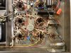
Finally, the old driver circuit of the new 6550 channel has all been removed, to make way for the new circuit. In normal development terms then, the land has all been cleared, and all the utilities are in: both heater and B+ sources are available or reconfigured as required, as are the input and feedback signals as well. All that remains then is to install the actual driver circuit itself, and adjust the NFB and stability circuits for it. Pics include:
1. The modified 8417 channel, now with the output tubes in line with the OPT transformer, and a more appropriate value DC balance control installed. The bias control for this channel -- which was mounted in the original gain control position -- and the AC balance control -- which was a PC type control soldered in place -- have both been moved top side now for ease of adjustment. This channel is now fully operational again.
2. The socket for the 6550 channel driver tube has had all the old circuitry removed, and is ready for the new driver circuit to be installed. The output stage wiring has already been tested, with the tubes biased and balanced at the initial set point for testing.
3. The power supply section, with the new B+ take off for the 6550 driver stage installed. It consists (in part) of the two blue power resistors, and Zener diode connected to them.
4. A full under-side shot of the Bogen as it now stands.
5. I know. It ain't pretty. But then the Bogen never won any beauty awards to begin with, either. And remember, this thing is first and foremost a development mule. In this case however, form does allow for necessary function. The output tube DC balance controls are in the same location as with the original design, while the new brackets (no holes needing to be drilled) hold the DC bias and AC balance controls for each channel, allowing for easy adjustment while working on the unit. The blue cap is mounted down with silicone, serving as the filter circuit for the new 6550 driver stage.
So, the modified 8417 channel is back in full operation again, while the new 6550 channel is rounding third for home now. Once it's finished out, then, some real comparisons can be made between the performance capabilities of the two different channels, and an ultimate decision made by rpampt as to which way to go. Following that, there are just a couple of issues remaining to address, but otherwise, I hope to be putting a wrap on this puppy in the next few days. Too many other projects are getting backlogged!
More soon.
Dave
Attachments
-
 Installing Bogen 6550 Driver Circuit 003.jpg128.7 KB · Views: 73
-
 Installing Bogen 6550 Driver Circuit 002.jpg121.6 KB · Views: 63
-
 Installing Bogen 6550 Driver Circuit 001.jpg118.7 KB · Views: 57
-
 Installing Bogen 6550 Driver Circuit 004.jpg120.8 KB · Views: 65
-
 Additional 6550 Driver Installation Pic 001.jpg98.1 KB · Views: 83