• The move to the new server is done. There are some software and database maintenance updates in process. This has us passing the hat around to help out. We appreciate any donations. Seriously, even a dollar helps. The payment page may be found here - https://www.audiokarma.org/support.html

The Official "Build" thread for the V4 WYN Phono preamplifier

Don't apologize, I did it, I think I overheated the transistor. No, I don't have a replacement, I ordered 10 pieces here in the Czech Republic, so I'll have them on Monday. For now, I'll deal with the mechanics. Thank you very much again.
Pavel ;)
 
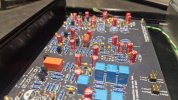
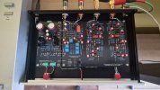
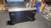
Hello, I've moved a bit. The Transimpendence MC Phono preamp V1 will be finished, but it will probably be tedious to properly finish everything mechanically at the level I chose. Everything fits well in the chosen box. Please do you have any ideas for switches that would be suitable for this. I have ordinary ones that don't really fit. Photo below. Greetings for now, I'm going to continue.
Thank you hirscwi!
Pavel
I've always wrestled with switches on those 10mm front plates. I've found only two choices, because the bushing on the switches are not long enough to fit through he plate. One option is to thread the hole and screw the switches directly into the plate. I've done this several times and it's not difficult. You can find the size/thread pitch on the data sheet (there are several in use). Then purchase the proper tap(s). Amazon is OK because you don't need high quality tap(s). The other option is to back-mill the plate so the bushing goes through the remainder. This is difficult to do unless you have a milling machine but easily done if ordering from Modushop or Front Panel Express.
 
Last edited:
Yes, I know, great idea with the thread into the panel. Thanks for providing the layout of this gem! I appreciate it.
Pavel ;)
 
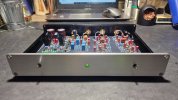
Hello, I replaced the Q37 transistor and everything works as it should. After switching on, I wait about 30 seconds and the relay switches on. Excellent. I'm happy. Thanks Wyn for the advice. I appreciate it. I put it off for a while, I got some flu. Today I revived it. Everything works, so I'll start working on the mechanics. I got a 1/4x40 thread tap for the switches. It was quite a PITA to get this thread tap in Europe, but I managed to do it. For now, greetings.
Pavel;)
 
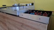
Once again I would like to thank wyn palmer and hirscwi. It plays very well and cleanly in the entire frequency range, very balanced, huge image to the sides and depth. It is very quiet. Transimpedance works exactly. You guys are doing an incredible job here for people. Thank you very much, I appreciate it. Sorry for the bad English, I use Google translator.
Pavel ;)
 
Once again I would like to thank wyn palmer and hirscwi. It plays very well and cleanly in the entire frequency range, very balanced, huge image to the sides and depth. It is very quiet. Transimpedance works exactly. You guys are doing an incredible job here for people. Thank you very much, I appreciate it. Sorry for the bad English, I use Google translator.
Pavel ;)
Thank you. To my knowledge only you, Bill Hirsch, and I have actually heard this beast working. I'm glad that it seems to be as advertised.
What input impedance have you selected, 0 ohms or 2.2 ohms?
By the way, have you made the change to the output protect circuit that was identified for the normal design? I would strongly recommend it.
 
Last edited:
What did I miss? Can the input impedance be changed? How? I probably chose 0 Ohm. I don't know. Resistor R23 is connected in parallel with diode D1, 1N4003. That's what I did. Can you confirm or deny this statement? Thank you.
Pavel
 
There is a 2.2ohm R in the layout in series with the input. It can be replaced with a short. I generally would recommend having the 2.2ohms in place, but it could be interesting to see if it matters. It acts to reduce the gain variation vs. cartridge source resistance, but also increases the input impedance from c. 0 to c. 2.2 ohms,
The 1N4003 is all that is needed.
 
2R2 Ohm left at the input. In this state I received the schematic so I did it that way. I'm not one to change the design. Is there anything else I should know about this MC preamplifier. Thanks.
Pavel
 
Hello, after listening for a while, I have to take my hat off to the gentlemen who created this masterpiece. It sounds incredible! Thank you,
Pavel
 
  • Like
Reactions: j!m
Hello, after listening for a while, I have to take my hat off to the gentlemen who created this masterpiece. It sounds incredible! Thank you,
Pavel
Thank you Pavel. The design seems to have gone dormant. Sota have had it and have listened to it and are interested in a production worthy version having conducted listening tests against a number of extremely expensive alternatives, which went quite well, but Bill Hirsch and I have minimal interest in doing the work for them and they seem happy to sell the inferior Pyxi (now at $450) and would reserve the new design for a high-end unit.
Bill has ongoing health/availability issues that has halted further development on the remote version, and I have little interest in pursuing the remaining development on my own as the actual circuit work is done. I have some interest in using AI (I have subscribed to ChatGPT and Claude) for coding of the remote, but only some, and not enough to work on it without the physical unit progressing.
So, this seems to be the end of the road. All who are using the units seem very happy with the outcome.
 
Back
Top Bottom