• The move to the new server is done. There are some software and database maintenance updates in process. This has us passing the hat around to help out. We appreciate any donations. Seriously, even a dollar helps. The payment page may be found here - https://www.audiokarma.org/support.html

The Official "Build" thread for the V4 WYN Phono preamplifier

Yes. Apparently, I've missed a 10 ohm R somewhere. I'll check.
There should be two per power supply decoupling stage, so it should be an even number x 2, or a multiple of 4.

Edit: Found it. The ground lift R, the one that's not in my schematics and I never use.
Thanks!
 
Last edited:
Yes. Apparently, I've missed a 10 ohm R somewhere. I'll check.
There should be two per power supply decoupling stage, so it should be an even number x 2, or a multiple of 4.

Edit: Found it. The ground lift R, the one that's not in my schematics and I never use.
Thanks!
Yes. I added that one and I don't use it either.
 
I recommend a modification to the v4 to avoid a potential failure mode that has been exposed in bench testing of two newly constructed units.
The amplifier stages were tested with bench +/-15v supplies with c. 50ms turn on time power supplies.
This caused, in one case, a catastrophic failure of a transistor in the unexpected power removal protection circuitry.
For existing units that employ the custom power supply I recommend the addition of a single diode, D1, a 1N4003 or similar, as shown below, the same type as used elsewhere in the circuit.
diode.png

This does not seem to be a problem in existing builds as the power supply turn on time is very slow, but I nevertheless strongly recommend the addition as the transistor Q39 can fail in unexpected ways and in one case the collector base shorted putting a near short between ground and the -15v supply. This would cause the -15v regulator to go into shut down and likely enter thermal protect, but it is in no way a good thing.
For those that use other +/-15v supplies I recommend a slightly more complicated change.
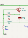
diodeplus.png

I will request @hirscwi to update the v4 layout with this.
I have updated the Kicad files with the schematic change.

 
Last edited:
It's one diode that can be tacked on top of the 5.6k R. No-one has had a failure that I know of.
Or you could just cut out Q39 and live with the consequences.
I’ll fix it.

I’ve already got to much stuff going wrong around here. Stereo downtime sucks.
 
20260314_130959.jpg20260314_131021.jpg

How to add the new components. Solder the diode across R23, taking care to get the direction correct, as shown.
Cut the -15v rail in two places, as shown. This disconnects the -15v from the protection circuit and the relay.
Solder the 1k resistor across the "upper" break, having scraped off the coating on the track and wetting it with solder. Check that the resistor is connected to -15v at one end and that the trace end is not shorted to the ground plane.
Connect a wire from the -15v end of the resistor to the relay -15v pad that was previously disconnected.
Operate the circuit. Ensure that the relay activates on power up after 20-30 seconds and that it deactivates on power down (listen for the clicks).
Quickly power up again. If the protect circuit is working properly the relay activation time will be about the same or a bit longer than before. This means that the control line has been forced to just below ground by the protect circuit when the power is turned off.
 
Last edited:
1N4003 added as advised Wyn and all good. Wired up the mute switch while I was in there too and all works as it should (hadn't got around to this before).
 
The 1k need not necessarily be 500mW. The peak power is 225mW, and that is only for a short time each instance when the unit is powered up.
500mW gives margin.
 
I have the layout revised for the added components (D1 and R33). I had to make the board a bit wider to accommodate (I think I originally got carried away making the board compact...)

I'll send to Wyn for his review and then he'll update in the dropbox.
 
I have the layout revised for the added components (D1 and R33). I had to make the board a bit wider to accommodate (I think I originally got carried away making the board compact...)

I'll send to Wyn for his review and then he'll update in the dropbox.
Thanks!
 
Wyn: Just catching up on the latest and found I have the incorret zener in D18. Will a in4148 work in place of the 1n914? I have lots of the former, non of the latter on hand. Thanks, Mike Barney
Don't swap it out. The zener does nothing to limit the voltage which is actually limited by Q1 turning on, and it just acts like a reverse biassed diode, and what we care about is limiting the forward biassed diode voltage due to charge from the protection cap. What is important is the extra diode etc. specified in the earlier posts.
 
Don't swap it out. The zener does nothing to limit the voltage which is actually limited by Q1 turning on, and it just acts like a reverse biassed diode, and what we care about is limiting the forward biassed diode voltage due to charge from the protection cap. What is important is the extra diode etc. specified in the earlier posts.
OK, thanks. Already added the diode in parallel with R23.
 
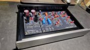
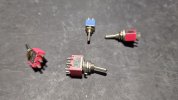
Hello, I've moved a bit. The Transimpendence MC Phono preamp V1 will be finished, but it will probably be tedious to properly finish everything mechanically at the level I chose. Everything fits well in the chosen box. Please do you have any ideas for switches that would be suitable for this. I have ordinary ones that don't really fit. Photo below. Greetings for now, I'm going to continue.
Thank you hirscwi!
Pavel

20260427_202005.jpg20260427_202412.jpg20260427_202519.jpg20260427_204202.jpg20260427_204217.jpg17773162925946361499854139616276.jpg
 
Hello, I've moved a bit. The Transimpendence MC Phono preamp V1 will be finished, but it will probably be tedious to properly finish everything mechanically at the level I chose. Everything fits well in the chosen box. Please do you have any ideas for switches that would be suitable for this. I have ordinary ones that don't really fit. Photo below. Greetings for now, I'm going to continue.
Thank you hirscwi!
Pavel

View attachment 3751095View attachment 3751096View attachment 3751097View attachment 3751098View attachment 3751099View attachment 3751106
Sorry. I don't have any specific switch recommendations. That has always been a builders choice.
However, it looks good. have you actually checked that it works?
 
Yes, tomorrow I'll revive the power supply first, then the others. But today I measured the ground against the +/- power supply of all active elements, checked the polarity, etc. Slowly but surely.
Pavel ;)
 
Back
Top Bottom