• The move to the new server is done. There are some software and database maintenance updates in process. This has us passing the hat around to help out. We appreciate any donations. Seriously, even a dollar helps. The payment page may be found here - https://www.audiokarma.org/support.html

The Official "Build" thread for the WYN Phono,Line,Warp,Headphone Pre amp

Nashou66

AK Subscriber
Subscriber
Here we will discuss our builds of Wyn Palmers excellent spec'd Phono pre amp.

This is the first thread of Wyns design mostly about v1.x its has lots of good info on why he started this project.

High gain op amp based preamp for low output MC cartridges.

And this is the second thread where he added new design elements from the first iteration which eventually became V2.0

Ultra high spec. op amp MC/MM phono, warp "elliptic" filter, line, headphone amps.


We will show how we built our units , what features we chose to use and how we went about implementing them
in our builds.

This is to keep the original thread just for the discussion of the actual electronics , the theory of its design any questions on the circuits and any analysis of its sound and performance.

So show us your builds and any current build your working on.

I will save the first few posts for my build. Cant do much today so they will be reserved.

Aslo I will include links from the original threads that I think are relevant to the build.

Grounding Scheme

What to do if you miss install an IC chip and how to remove it using a heat gun

Good info in Wyn's thread on the choices for the op amps and why they are used for each stage

https://audiokarma.org/forums/index...ne-headphone-amps.937686/page-9#post-14376916

Some have been asking about what parts I used for the chassis ands other supporting pieces etc. I will list then here. most are from eBay so I'll post pictures and search words.

Parts I used for the build not including the boards or electronic parts for the boards.

4 way Audio input choose board/ Stereo Audio selector switch board for AMP DIY

51000864201_c54747e9a2_c.jpg


Full Aluminum amplifier Enclosure/mini AMP case/ Preamp box/ PSU chassis WA12

51000182478_d6417f9710_o.jpg


1PC silvery solid aluminum volume potentiometer Knob for Guitar loudspeaker

Look at size, 38mm fits the chassis above if you want to use these knobs, they are not painted as the ones supplied with he chassis. Both are nice but if you need a third knob this is the closest to style. they also have 30 mm if you want the third knob to be smaller.

51000191383_e81d591598_o.jpg


20 x CMC Gold Plated Copper RCA Female Phono Jack Panel Mount Chassis Connector

These can be soldered right to the relay board and then the board can be secured to the rear bulkhead vie these RCA's that have the threads on the back panel and not inside the chassis. This would make repairs and installation much easier than the route I went not he first build I did that are in the following posts.

51000907436_2e35b8957a_c.jpg


EDIT 6-23-2021 :

Version 2 Drop Box BOM's

https://www.dropbox.com/sh/3ax8p175lu2izoc/AADfl-SVvf84CR37Ra2lGMjla?dl=0

Version 3 Drop box BOM's ( you'll need
the build guide for V2.0 for V3.x as well)

https://www.dropbox.com/sh/92gig3oftxjqi9w/AACbKqpwnxBSPys9XDdVbqqSa?dl=0


Edit: 11-10-2021

Headphone amp board schematic

51671402809_6b50bf2c42_h.jpg


Athanasios
 
Last edited:
Register to hide this ad
Chassis from the bay , nice quality.

50804127883_c377a67a35_b.jpg


The Chassis for the build!!!

WOW this is much nicer than I thought. Worth the $251 shipped for two units to the USA.


Well packed too!!!

50804990907_2e96b6d685_c.jpg


Nice thick front plate 7 mm and 3mm rear plate.

50804127838_03f2063915_c.jpg


50804990917_71c6e9fb17_b.jpg


Tops and bottom are also Aluminum 2mm thick .

Reminds me of my Yamaha T-2 Tunner chassis. Just as nice .

Now to wait for the Push button switches for the MC/MM, Mono, Warp on/off, warp gain 0dB/10/dB and its mounting hardware so I can
measure the location of the 4 holes needed.

Going to add more jacks on the back as well. And another front rotary switch . Need to find a similar knob for it. Maybe the seller has an extra I can get. Didn't realize Id need more than is already there. :D

This is going to be an epic build, I hope my goals aren't going to compromise the work Wyn put into the electronic design.

Athanasios


Using printed cut outs to try to figure out the layout. I want to have use of all options and more!!!!! :D

  • MC/MM switch w/ LED indicators
  • Warp on off switch
  • Warp gain switch
  • Mono switch
  • 4 MM phono inputs via DC powered relay switch board
  • 1 or 2 MC inputs most likely a push switch possible LED indicator
  • Source switching for the 4 phono's( one position needed for this) , AUX and TUNER
  • Headphone output with its own volume control
  • Dual gang Main volume control
I think that is it !!!

Dont have it all drawn in yet and , mind you, this is just a rough draft :D

50767986918_6ce614c3a4_h.jpg


Yes I am crazy!!!

Athanasios
 
Last edited:
For those who have the v1.3 boards @HalfApt ( Sean) came up with a mini daughter board to allow the older V1.3 boards have the ability to use parallel op amps which are better than single.

Her is a post from that thread..............

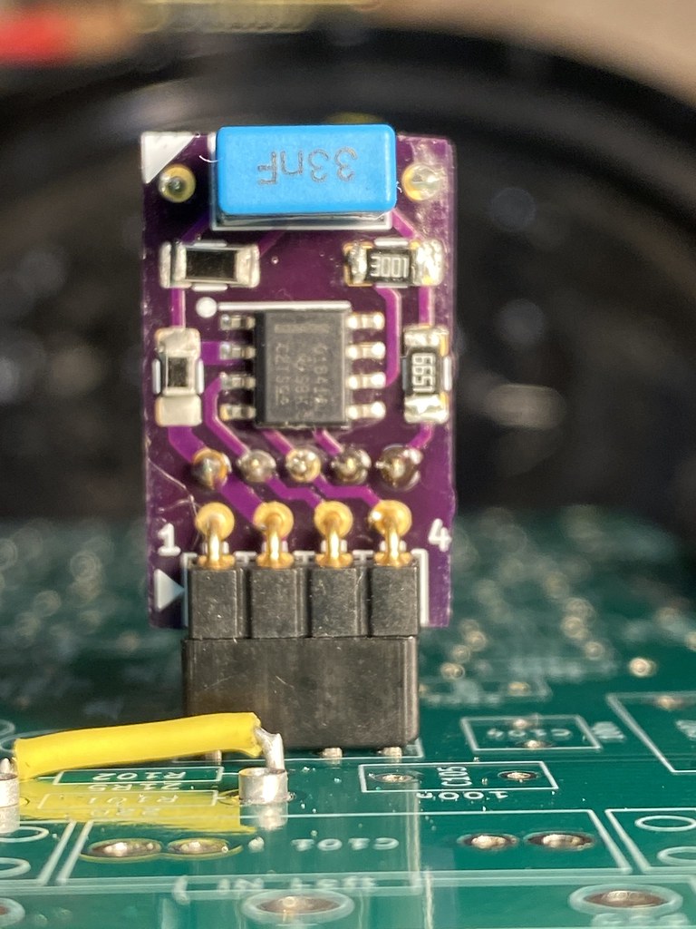
I built one of the MM Parallel daughter board assemblies for the v1.3 boards.

@HalfApt , I looked at R5 on the main board and it was 3k so I took the liberty that the SMD resisters R5/6 ordered were suppose to also be 3k and not 75 ohm .

Also in the build notes you gave, it looks like the L headers touch in-between the boards and obviously they shouldn't ....correct? So I cut them short as not to touch.

I figured out the best was to solder the parts on was to first use solder paste for the op amp, then do the resistors then cap and headers with the two support pins
at the top last, which one I lost. So I used resistor lead. Solder paste does not work for the SMD resistors , as it heats up it bubbles and pops and flip the resisters over.
I probably could hold them down with a tool but doing the same with regular solder and thin iron tip worked out fine.

When soldering the joining header, first solder it on one board and make sure its square. Then use the socket on the main board or if you have an extra use that
to align the distance between the two boards. I added a small piece of foam towards the top of the board to separate it up there while soldering the second board to the existing soldered joining header trying to keep the boards evenly distanced along the entire length.

Here are some pics, this did take more time than I thought it would for so few parts. I 3 more assemblies to build .

50829290558_0de1ddd262_h.jpg


50830034706_01c4f10eb2_b.jpg


50830123527_103104d306_b.jpg


50829290573_7dd544a00b_b.jpg


One MM v1.3 board now a parallel amp board just like v2.0 ( minus warp filter) .

50830293631_58529fe4ae_h.jpg


50830380332_ecad039475_h.jpg


50830380352_8937bf9765_h.jpg


Athanasios
 
Last edited:
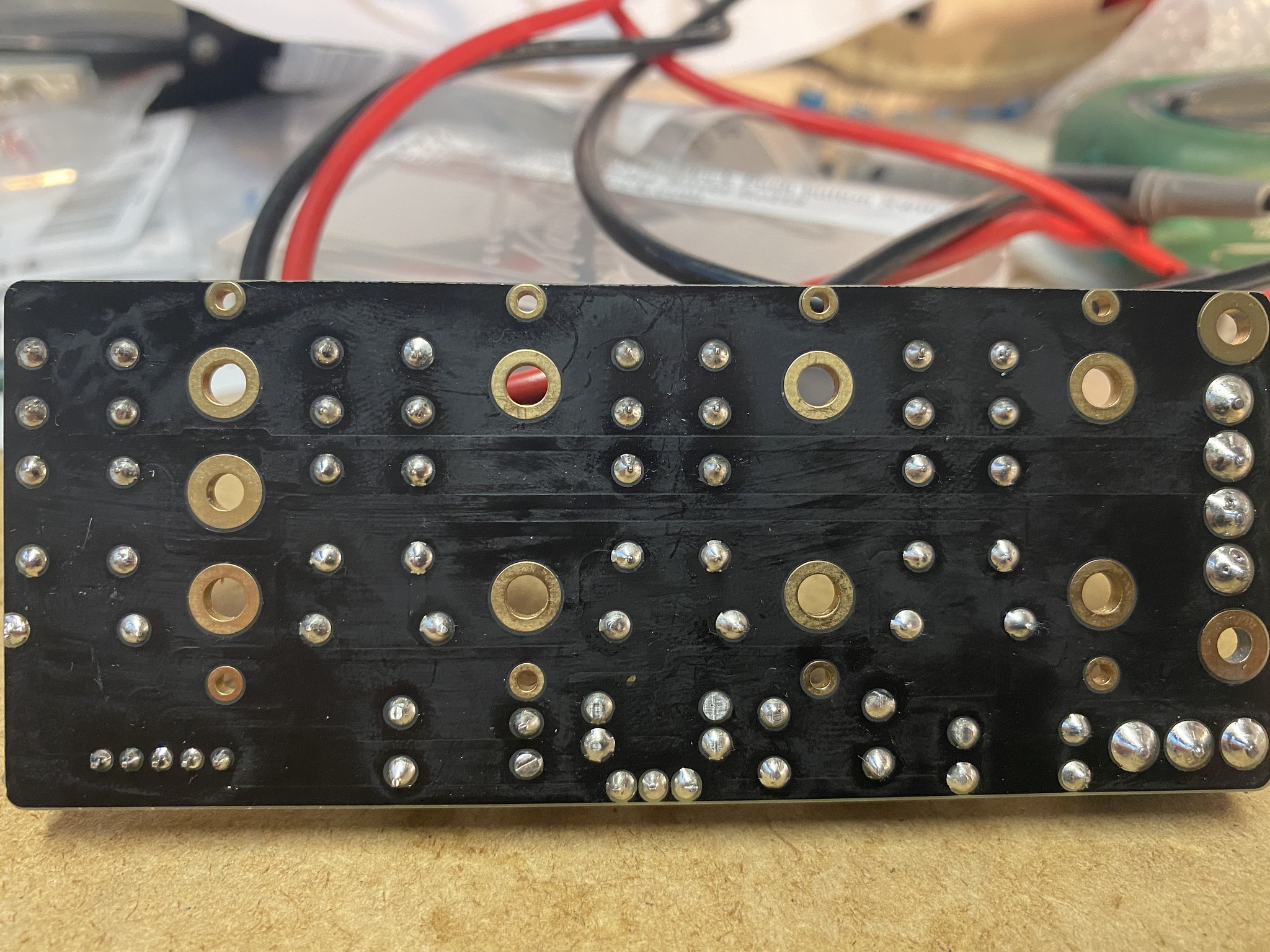
Did you get a schematic with the boards? If not, and if you can get good straight-on close-up photos of both top & bottom of the relay board, I might be able to figure out the schematic.

When you first posted about this relay board, I thought you were planning to mount the RCAs to the board. That option is clearly intended, as evidenced by the hex nut outlines on the silkscreen.

But if mounted to the board, then the RCAs can't be chassis mounted, unless you use RCA jacks with exterior threads.

Are the board mounting hole pads connected to ground? If so, the board will have to be mounted on insulated standoffs.


No Schematic. But I just tested if the GND for the inputs has continuity with the chassis , and it does not.

But here are pics of the front and back. One thing though is these PCB's are thick and hide the traces, unless you can make out the raised areas, those are the traces.

Also it says 12 vac but in the Bay description it says it accept 12-15 DC as well.
But looking at the board I was wondering if I can connect the DC to the board after the rectifier diodes since there is no need for rectifying the DC source.
And if So how would that be done?

Click for large pics

50860885101_bc145ee0d7_k.jpg

50860983322_0bee0a52b3_k.jpg


In this next pic you can see that I can mount it to the current RCA's . The signal is easy to connect but for the GND's I'll have to use wire jumpers from the RCA's to the board. No biggie.

And @mkane gave men\ an idea as well about using parallel load resistors. I can run the outs from the relay board to a rotary selector switch right next to it with
a set of parallel load resisters 10k, 47k and 100k .


Here is how the board fits perfectly on the RCA's

50860885101_adb5a6b348_h.jpg


See how the signal soldering pins fit perfectly in the holes. I will just bend the GND lugs flat so they do not touch the board and solder wire jumpers that will come from under and over
the board to the front. Solder to lugs first, fit board, solder signal pins then GND's . . I may desolder the power triplet and flip it so I can access the connection with out having to either remove the bottom panel or desolder the entire board.


And here Is how I think the new layout inside would look now with board on RCA's.
Except I'd flip the MC board around so the inputs are at the back panel.

50860904566_566d0338cf_h.jpg


Lots of work but I think this will be an epic build.

Might hold off on the Loading resister idea for now.


There's no reason to connect the DC source after the diodes if the DC source is within the specified operating range of the unit. All that happens is that a diode conducts and drops the DC voltage at the output down by 0.7v or so.
Where is the 15v coming from- is it the usual SMPS? Do you know how much current the switching unit takes?
My apologies if you have already answered this, but I can't say that I've been paying careful attention to what you are doing here.


You could just use a current meter to connect the SMPS 15v supply to the relay board and measure the current. Just a standard multimeter should be able to do it.

About 23 uA, however the rotary switch board has LED indicator bulbs for each input.
I dont have to use them I dont think.

50861169882_e16f2636af_b.jpg
 
Last edited:
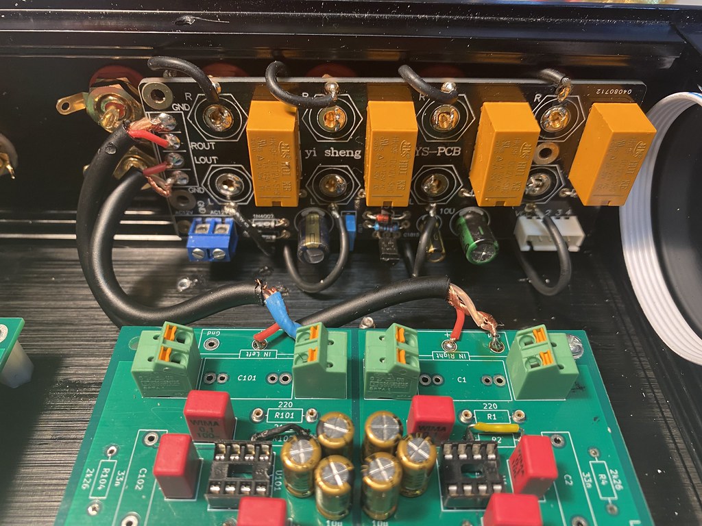
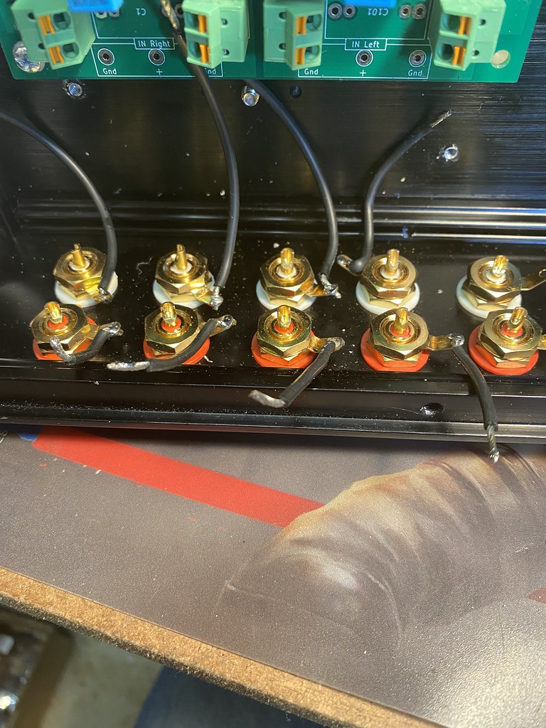
Was back at it tonight. Wired in the input wires for the relay board to the MM board and the single MC input.

First I had to solder in GND jumper wires to make it to the front of the relay board.
I forgot to connect each GND to each other , But I addressed that later....I think its ok how I did it.

50868812167_cdd14cff6c_b.jpg


Then I fit the relay board over the socket pins and solder in the jumpers and center signal pins.

50868715136_5f84232769_b.jpg


Here is the outs from the relay board to the MM board.

50868812132_fb623da246_b.jpg


Here is the MC input soldered to the MC board and how I dressed summing the R to L GND's , on the relay output I solder a jumper to the L and R GND out, the thiner red wire . I think this will be ok as I tested and all GNDs are connected not via the relay.

50868812107_406009a0c3_h.jpg


And here is a shot of both boards connected to the inputs.

50868715096_9762855e4a_h.jpg


I used Mogami Microphone wire for all the inputs and will use it when I wire each board to the MM/MC switch and back the the Line stage
on the MC board.


Took me some time as it was difficult to solder the relay board up, especially the bottom GND's. Only after I was done I realized I could
have removed the bottom for easier access to those solder points.

Also on the relay board I removed the triplet power connector and put in a dual and revered the input side for easy connection. This board only needs a GND and + 15 VDC connection.
Also removed was the output block terminal , that is where the outs were soldered directly to the board.

Tested for any shorts that may have occurred between signal and GND and the input GND's to the chassis. No continuity there so so far so good.

Athanasios


Last edited:
My build has been sidelined for over 2 months while I've been focused on building and installing a fast street motor and modified gearbox in our Alfa Romeo GTV, and smaller electronics projects that don't take more than an hour to complete. The attached photos therefore show the incomplete state of wiring, which is the last step for this project.

This chassis is similar to that originally suggested by Wyn and which I used for my first build. This one adds relay switching components similar to yours, Athanosios, but slightly different. Because I wanted to isolate the MC input jacks and use the relays only for other inputs, I mounted all RCA jacks on a subpanel after machining the rear panel. The relay board shares the grounds on all RCA jacks, which I suspect yours does as well, which is why I went with two separate input jacks for MC. For this build I'm only using one set of output jacks. This version of the chassis doesn't come with a separator, so I made one of aluminum plate. Machining was done using various bits and tools with my milling machine, followed by some hand finishing.

The relay board is powered separately, because I didn't want additional draw from the main PS. I bought a very small PC mount toroid transformer, made a perfboard for it, and covered it with an MU metal cap. Each of the LEDs draw more current than each of the relays, so the separate power supply seemed a wise choice, despite not being an SMPS to match the PS of the preamp assembly. The included rotary switch didn't have enough positions so I used a high quality switch with enough positions and allowed me to include connections to a little daughterboard for LEDs and dropping resistors.

Lots of fiddly wiring remains for the warp filter switching, hooking up the HPA, PS, etc. and then I'll bundle wires for better appearance and performance. Hope to complete this in a month when my Alfa project, work demands, and some medical issues are resolved.

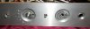
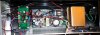
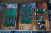
DSCN0641a.jpg DSCN0639a.jpg DSCN0638a.jpg DSCN0637a.jpg
 
Last edited:

My build has been sidelined for over 2 months while I've been focused on building and installing a fast street motor and modified gearbox in our Alfa Romeo GTV, and smaller electronics projects that don't take more than an hour to complete. The attached photos therefore show the incomplete state of wiring, which is the last step for this project.

This chassis is similar to that originally suggested by Wyn and which I used for my first build. This one adds relay switching components similar to yours, Athanosios, but slightly different. Because I wanted to isolate the MC input jacks and use the relays only for other inputs, I mounted all RCA jacks on a subpanel after machining the rear panel. The relay board shares the grounds on all RCA jacks, which I suspect yours does as well, which is why I went with two separate input jacks for MC. For this build I'm only using one set of output jacks. This version of the chassis doesn't come with a separator, so I made one of aluminum plate. Machining was done using various bits and tools with my milling machine, followed by some hand finishing.

The relay board is powered separately, because I didn't want additional draw from the main PS. I bought a very small PC mount toroid transformer, made a perfboard for it, and covered it with an MU metal cap. Each of the LEDs draw more current than each of the relays, so the separate power supply seemed a wise choice, despite not being an SMPS to match the PS of the preamp assembly. The included rotary switch didn't have enough positions so I used a high quality switch with enough positions and allowed me to include connections to a little daughterboard for LEDs and dropping resistors.

Lots of fiddly wiring remains for the warp filter switching, hooking up the HPA, PS, etc. and then I'll bundle wires for better appearance and performance. Hope to complete this in a month when my Alfa project, work demands, and some medical issues are resolved.

View attachment 2108354 View attachment 2108355 View attachment 2108356 View attachment 2108357

Nice, I almost bought that chassis but went with the one that had the divider.

For the relay did you try to power up all the boards with he SMPS and it was too much or did you just start that way just incase?

Athanasios
 
I would have as well, but didn't find it when I bought that one.

No, didn't try to power up everything because I didn't want to go back and remedy the situation if the current draw was too much. Also, based on Wyn's advice and calculations, I realized powering a relay with an additional LED was going to pull more current than I wanted for headroom. OTOH, waiting for the transformer to arrive also slowed down this project, which I started many months ago. Good thing I have my first build and 9-10 other preamps to play with, and a constant supply of repair and upgrade projects. :)
 
I would have as well, but didn't find it when I bought that one.

No, didn't try to power up everything because I didn't want to go back and remedy the situation if the current draw was too much. Also, based on Wyn's advice and calculations, I realized powering a relay with an additional LED was going to pull more current than I wanted for headroom. OTOH, waiting for the transformer to arrive also slowed down this project, which I started many months ago. Good thing I have my first build and 9-10 other preamps to play with, and a constant supply of repair and upgrade projects. :)


Ahh....Well I'm going to give it a shot. Maybe I'll get lucky. the relays seem to only draw 23 uA . How much do the LEDs for the rotary board draw each?

I wonder if the Mean well Current is limited by a circuit of the size of the heat sink. I know when I built a few AMG sigma 11 PS's you could get more current by increasing the heat sink size.

Athanasios
 
I like your idea of putting the relay board on its own sub panel. I could maybe do that on my next build . Or just find another way to line up the GND's for each socket.

But I am using the relay only for MM inputs. My one table has two arms and I have two other tables near by I could hook into this preamp. The MC will be a single input for now.
As I have a SUT I could alway add into he left over MM input.

Athanasios
 
The RCA jacks supplied with the relay board are front-mounted, and designed to fit perfectly with the board for soldering both signal and ground - no additional ground wires needed. I'll post a photo later.
The subpanel was needed just so I could fit everything needed.
 
What is the benefit of the relay instead of just a physical rotary switch?


For one, less wiring. Only one output to either MC or MM board or Line section. With a rotary you'll have as many input wires going to the switch which would be up
on the front panel. This is just neater. Might be an audio benefit as well as these relays are sealed , so theoretically no corrosion on the signal contacts.

Athanasios
 
+1, Athanasios. Deletes many inches of wire. Good quality relays are essential, and some designers eschew relays because of potential signal dropout, but relays are used in a lot of high-end and professional audio gear.
 
Thanks. Since mine is already wired to a physical switch I won't worry about it. Just wanted to make sure I wasn't missing any benefit other than cleaning/simplifying the wiring.
 
As I have more time and go through both threads I will update the first post with links I feel are needed to help with the build as I myself am still in the process
of completing a working unit.

lets get more builds to show up here guys!!

@wyn palmer said there are 200 plus boards out there, lets see what you guys have done no matter how they look. It matter more about how they sound to you.

Post those listening results here and as well on one of Wyns threads. I am sure he'd appreciate any feed back on his extensive research and testing of this awesome design.

Athanasios
 
+1, Athanasios. Deletes many inches of wire. Good quality relays are essential, and some designers eschew relays because of potential signal dropout, but relays are used in a lot of high-end and professional audio gear.
My old ADI colleague and collaborator, Walt Jung, declared after much evaluation, that each conventional switch in the signal chain degraded the audio performance significantly.
Certainly exposed switch contacts have the possibility of corrosion and the acquiring of some non linear (rectification) properties, and the resistance is non zero, but I have seen little evidence for this as a generally true statement. Certainly using sealed relays allays some of these concerns, and using the switches to short to ground rather than go open also tends to be a better approach. Also switching into relatively high impedances has advantages (and disadvantages).
The phono stage/preamp normally has only two switched sections- the Warp filter (in/out and gain) where the switching is either to ground/open or with only the LF warp signal in series- or the input selection function for the line stage.
In general, in my opinion, relays are better than mechanical switches when small signals are being switched.
In my own preamp implementation I have used a similar relay bank to provide source switching for the line stage.
 
Thank you Wyn.
In a few of my preamps and a Bryston crossover with wafer switches, even enclosed versions (but not sealed), I've found distortion and signal dropout using my oscilloscope. The worst was the Bryston, despite the high quality switches used, probably because it had been sitting in an attic for 20 years. That was the least of the problems I had to solve, but it took several cleaning and lubricating cycles to get a clean signal.
 
Back
Top Bottom