
• The move to the new server is done. There are some software and database maintenance updates in process. This has us passing the hat around to help out. We appreciate any donations. Seriously, even a dollar helps. The payment page may be found here - https://www.audiokarma.org/support.html

The OFFICIAL MSM5540RS/M5540 Sansui Gx700 40pin IC Thread! NUDIES

One more step closer to understanding the FLL loop filter. This has two time constants that are selected with the KILL signal (TR16 and FET01). When the loop is open the time constant is a few seconds:
250303-070315_0x10_step_kill.png

Once KILL goes off it is a few minutes:
250303-073003_0x10_step_no_kill.png

This means that my FLL must set the PWM output to the right value once KILL goes off. This seems to be what the MSM seems to do in any case:
250211-082344_msm_fll_lock.png

So my code must anticipate the final value and set the PWM accordingly. The first FLL_IN value is leading and the tuning voltage should then drift towards the center frequency (0xC0). Hm. No idea where to start. Will park it for a while now.
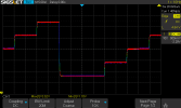
 
I realized something important: if I am to create a predictive PWM value I must take into account the VCO frequency. After all, a VCO is more sensitive for voltage control at its upper end because of the total capacitance being lowest and a capacitance change of the varactor creates the largest frequency change. So I made a test to step the PWM voltage and record the frequency changes:
250305-072800_FLL_step_test.png

The result is interesting. A step from 0x2F (¾) to 0x0F (¼) yields a step of 100 kHz at 88 MHz, 150 kHz at 98 MHz and 200 kHz at 108 MHz. It is nicely linear which makes calculation of the predictive PWM voltage step easier. Once the step is made and the time constant of the FLL filter becomes very long the FLL just has to compensate for drift. Any tuning action will cause KILL to become active, shorten the time constant again and moves the PWM voltage to the center value (0x1F). The actual MHz value is known (from the frequency display) so that will be used as compensation for the predictive PWM voltage value. Of course there are large tolerances but they will have to be dealt with once the FLL drifts to the set frequency (0xC0).

I have no idea how the OKI engineers solved this problem. From the scope screenshots I cannot figure out how it does the predictive step it has to make. But that is your typical black box reverse engineering.

To be continued...
 
While I don't have any updates on my algorithm I did get a third T-80 with no quartz lock. It looks like in this case the DAC is OK and the MSM is not borked as it was in the other unit. The DAC creates a monotonous step signal if I rotate the tuning knob and the lock window is active (LOCK pin high). The LO goes all over the place if I don't force the tuning voltage to a fixed value (7 V). This suggests an issue with the low pass filter.
 
I may have found a way to do the calculation for the PWM (VCO) value before KILL goes high: I will just write a simple PICBasic program, compile it and paste the resulting assembly code in my own program. Easy peasy! The formula is PWM = (ERR/SENS)+0x1F, where ERR is the difference between wanted and actual frequency value (wanted is 0xC0), SENS the correction for the sensitivity of the varactor. I did some testing and the empirical formula becomes SENS = 8*(INHI+0x13)/0x7C where INHI the high byte is of the prescaler output, something like 0x69. I lost the piece of paper where I jotted down the values for 88, 98 and 108 MHz. I prolly will need to change the constant 0x7C and also cater for the FLL hunting for the correct frequency while KILL is low. I guess I will have to test for ERR being negative and handle it separately.

Once the lowpass filter goes into long time constant (KILL is high) the FLL only needs to adjust for drift. Once KILL goes low again for whatever reason (touching the tuning knob for instance) the whole circus starts anew.
 
It's remarkable that so much mathematical wrangling is needed just to replicate this one function. Leaves us to wonder how it was implemented in the original silicon. Obviously being a 40 pin DIP, it was a fairly advanced device. But now I'm wondering if the MSM5540 was actually more of a small scale microcontroller containing ROM, rather than simply an application specific linear IC. A strange beast indeed.
 
But now I'm wondering if the MSM5540 was actually more of a small scale microcontroller containing ROM, rather than simply an application specific linear IC. A strange beast indeed.
It could very well be. The technology at the time certainly made that possible. Whether custom silicon or something mask programmable like the Mostek MK3870, it could be anything. There is most certainly some complex digital trickery going on inside it. Reverse engineering its functions (frequency counter/display, fast lock then slow drift compensation) sure is a voyage that I had no idea where it would take me. Strange beast for sure. And I'm not done yet...
 
Oh wow... I have written the formula in PICBasic. Three lines of code produced a 111 opcode program with 18 variables. It will be interesting to see how this integrates with my own code. There is quite a bit of overhead (macros) that is not used in the actual generated code and I expect that this can safely be discarded.

For the code junkies among us attached the compiled pwmcalc.bas program-
 

Attachments

Finally figured it out! While my radio shack was unavailable due to a renovation I concentrated on fixing the code. Turned out my PICBasic formula was wrong. It took me some time to figure out the correct formula, convert it to PICBasic (attached) and insert it in my own code. I discovered that you must write the PICBasic with RISC in mind so a formula needs to be broken down into manageble chunks of code so the compiler has to do as little work as possible and thus generate very compact code.

I realized something else. The KILL signal is named wrong because it is not what it does. It only signals the micro to stop hunting the VCO frequency and go into a nudge mode that only compensates for drift with a very long time constant. If the tuning goes into the LOCK window the PWM must perform a step to put the VCO in the middle of it and then wait for the KILL signal to become high. If it goes low while inside the LOCK window it should keep the same PWM value. Once it goes outside the LOCK window and into the next, only then PWM must make another step.
 

Attachments

It's remarkable that so much mathematical wrangling is needed just to replicate this one function. Leaves us to wonder how it was implemented in the original silicon. Obviously being a 40 pin DIP, it was a fairly advanced device. But now I'm wondering if the MSM5540 was actually more of a small scale microcontroller containing ROM, rather than simply an application specific linear IC. A strange beast indeed.
I've been convinced from the very beginning that it's a controller that has ROM and some small RAM inside it.
 
Another update. Still trying to wrap my head around how the MSM does the locking and drift compensation. The KILL signal is actually named LOCK RELEASE in the TU-919 block diagram. However, this still is not what it does. Exactly how it does work is hard to understand because there are several states the system can be in. Observing how it behaves while moving from one state to another is not easy. I've installed LEDs on the LOCK and LOCK RELEASE lines but they are inside the tuner and obscured when I look at my instruments. I now have the MSM tuner on my workbench to try to figure out exactly what behavior I have to replicate.
 
Good to hear you are still at it. I was wondering if you'd hit an insurmountable snag, since you hadn't posted in a few days. It would be great if you can get this project to a point where it is production ready. Since the supply of NOS MSM5540 dried up, I'm sure there will be some demand for a replacement, even with the popularity of tuners in decline.
 
Another update. Still trying to wrap my head around how the MSM does the locking and drift compensation. The KILL signal is actually named LOCK RELEASE in the TU-919 block diagram. However, this still is not what it does. Exactly how it does work is hard to understand because there are several states the system can be in. Observing how it behaves while moving from one state to another is not easy. I've installed LEDs on the LOCK and LOCK RELEASE lines but they are inside the tuner and obscured when I look at my instruments. I now have the MSM tuner on my workbench to try to figure out exactly what behavior I have to replicate.
Astounding work!! I'll be wanting to purchase a few if you ever get to a point where its stable and functioning well, there are times when I have MSM faults come across my bench....
 
I'll likely be in for one or two myself. While I do little radio listening anymore, and have thinned out my collection of tuners a bit, I keep a couple of TU-919's, a 719 and an A-80 since they are each part of complete matched systems. I do have a few NOS MSM5540RS on hand, but don't feel I can truly trust them long term given their apparent age related propensity to fail spontaneously without warning.
 
Heh- I was a bit off the grid because of a renovation of my house... Did do some work during that but did not have access to my workbench. Anyway, reverse engineering is really hard and I am still a long way from understanding the operation. And how it interacts with the surrounding hardware.

I am determined to complete this project and have a sellable kit available. Eventually. Right now I will test until I fully understand what I have to replicate. Once I do that, I am done. Plonking in the diode matrix and fixing the hardware will be a piece of cake.
 
Another minor update. The third T-80 I got was misaligned (T02) and is now fully functional with quartz lock and all. I've observed the behavior of the VCO with my spectrum analyzer and it is much faster than the one with my drop-in replacement. I must figure out why that is. The MSM DAC only has 16 steps whereas my PWM has 64. It also steps every 100 ms and I step every 570 ms. That could be an issue. Maybe I can speed it up with some trickery. The frequency counter has 250 ms gate time during which I can safely handle the FLL every 100 ms. I will have to start all over again with the calculations...

I've modified the circuit around the opamp but I am going to reverse it because it won't be a drop-in replacement if any modding is needed. I also found a nice way to test the locking behavior: just switch to AM and then back again to FM. The circuit must re-acquire lock and then hold it.
 
Very good to see you are still at it. I can imagine it getting a bit discouraging by this point, especially since you've gotten so close only to be hung up by a couple of details. Reminds me of some Arduino based projects I've done in the past that I had almost done, only to run into a snag that took days or weeks to figure out. That sort of thing can really kill ones motivation.
 
No news on the PIC front. I've made a whole slew of screenshots to figure out how the PIC should behave while locking but I have yet to even start looking at them. Too many other tasks and projects... I did install a 40-pin socket in my third T-80 so I can easily swap the MSM and my PIC board. So there's some progress after all. :cool:
 
Hi All,

This thread is thread has been incredibly resourceful! I have been working on a clients troublesome 5700 digital section. I have had issues with the prescaler on my 6700 and chip on some others. This unit has similar issues as others have shared with locked digits and no quartz lock. Assuming the main chip, I installed my spare and no changes. Assuming it may be similar to my 6700 with a chip issue on the prescaler. I ordered some spare AN ICs on ebay and some counters from digikey.

Checking voltages on the prescaler and it seemed there was low power to the decade counter but schematics are not great so who knows?! Tracing the 5v power supply I came to the first coil and voila! This thing is short and eating all 5v! Once I replaced the coil, everything came to life again on the 3000 board! Digits working and quartz lock is back.

Just another possible culprit with these tuner sections.
 
Back
Top Bottom