• The move to the new server is done. There are some software and database maintenance updates in process. This has us passing the hat around to help out. We appreciate any donations. Seriously, even a dollar helps. The payment page may be found here - https://www.audiokarma.org/support.html

The synopsis of a Yamaha B-1 restoration

I've always been impressed by the attention to detail from everyone posting here. Thanks for the knowledge over the years. I'm not a VFET guy so I try and keep my redneckisms away and just enjoy the reading.
Gotta a couple questions:
-If I should come across some VFET power amp bargains one day, what are they? I'm aware of B-1, B-2,B-3, B-6 I think? . Anything else to look for? I know they're out of my league but your threads & videos are there for assistance.
-35 years ago my instructor said something that always haunted me. He said the N & P type doping material in semiconductors crystallize after 30 years from the on/off heat cycles. Does that explain the black lead tranny's? Just wanted opinions on that before I get involved in VFET, if I ever do, in a non thread crapping way if I may.

Good stuff here from ya'll on this side of the Yamabar, the next round is on me one day,
:beerchug:
 
  • B1 in foil or bag to prevent foam, dust, other unwanted particles to enter the unit,
  • 2inches of semi hard foam around the unit
  • Thick carton box
  • 2in semi hard foam around the first carton box
  • Second thick carton box
  • Use tape and straps around the second box for better containment but also for places to grab the box for the shipping gorillas.
  • It is imperative that the unit is super snug inside the wrappers and that the foam is neither too soft to collapse or too hard so that if there's external impact, it is not transferred to the unit.
  • Cutouts for feet and knobs, buttons is very beneficial.
Funnily @Bratwurst7s followed these exact steps on the C-1 prior to your response - incl. two grades of foam, double box, knob cutouts, straps, etc.
Great minds and/or equal OCD levels.
:biggrin:


I've been the lazy one on getting this B-1 over, not him.
A big thanks for the support from both of you over the years.

-If I should come across some VFET power amp bargains one day, what are they? I'm aware of B-1, B-2,B-3, B-6 I think? . Anything else to look for? I know they're out of my league but your threads & videos are there for assistance.
-35 years ago my instructor said something that always haunted me. He said the N & P type doping material in semiconductors crystallize after 30 years from the on/off heat cycles. Does that explain the black lead tranny's? Just wanted opinions on that before I get involved in VFET, if I ever do, in a non thread crapping way if I may.
Only B-1, B-2, B-3 are V-FET
  • B-2 is arguably the sweet spot (across all brand V-FET amps, not just Yamaha) in many ways:
    Rebuild cost / difficulty, aftermarket support, bass control across a variety of speakers, ability to keep itself alive (prior to rebuild), production volume
    • Confirm it comes out of protection and ideally that it hasn't been repaired
  • The output devices are robust and will outlive you if the rest is built right
    • Problems are more common with small-signal transistors (on 70s amps in general, not just V-FET amps). Common degradation modes are from the outside in (lead oxidation / corrosion eventually results in hermetic seal failure of casing, followed by lead-wire or die contamination/deterioration). Gain depletion is also possible, though usually due to insufficient de-rating at design phase
    • Contrary to popular belief there are many intermediate/intermittent failure modes in transistors but these are rare in output stage devices (assuming output devices were not abused, eg. loss of gate voltage)
    • Everything you actually need to worry about is covered in rott's B-2 why and how thread
  • Definitely not out of your league, just take your time and don't cut corners on the rebuild
    • Alongside most 70s amps, you get out (in sonics) what you put into the rebuild
    • Main filter caps on all units are now well past their use-by date, also budget for the upgraded input selector board at minimum
 
Last edited:
I should add that rott has very kindly offered to replace a now unobtainium B-1 capacitor for me, which mouser had packed insufficiently and as a result got damaged in the post. I was kinda bummed about it, but now another unit can hopefully live :angel:
 
Some progress on this front....

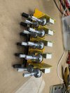
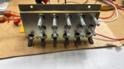
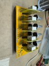
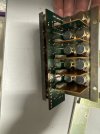
I am excited to announce that the pesky UC-1 switch assembly has been conquered :beatnik:

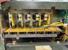
some background: the original UC-1 uses five sets of mechanical switches to route signal between input, via the pots, to the output. These five sets of contacts are layed out in a daisy-chain formation. What this means is that if one contact is bad, let's say on bank 2, than all other banks will suffer. This is a problem and a liability.
Here comes the replacement, configured to use sealed relays for low-level signal and multiple contacts of the old open to air switches configured in parallel (for redundancy) to only handle 12VDC for the relay coils....Voila'

IMG_8055.jpeg

DAB0B88E-66DB-45D5-88DA-8FD6A5A56555.jpeg
3B13661E-7B7D-48A7-9D0E-7EC3D0F899BE.jpegIMG_8056.jpeg
 
B-1 trivia:

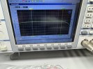
B-1 frequency response is nearly flat (less than 1dB drop) all the way to 100kHz

IMG_8129.jpeg

Note that the B-1 is at all times input coupled, hence a minor ramp up in the sub-sonics region
(the cursors here are not in the right place)
 
Last edited:
First listening session on one of mine tonight:music:

ZJtIZDh.png


Big thanks to rott for nudging me towards the finish line
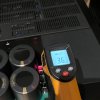
while your amp is running for 30+ minutes, use a thermometer to check temperatures at the top metal bracket of the -200v PSU and post your findings here.
 
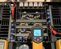
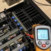
All closed up now but as you can guess I did take some temp readings.
Note this high temp is directly at the -200V PSU resistors (highest reading I could find).

Main heatsinks seemed stable at 50-52°C

IMG_3420e.jpg IMG_3409d.jpg IMG_3457d.jpg

Added one of rectifiers as we were talking about them
 
Last edited:
All closed up now but as you can guess I did take some temp readings.
Note this high temp is directly at the -200V PSU resistors (highest reading I could find).

Main heatsinks seemed stable at 50-52°C

View attachment 3553383 View attachment 3553377 View attachment 3553388

Added one of rectifiers as we were talking about them
The temp on the heatsinks can become higher if you push the amp or you bias it a bit differently, but that is okay. Vfets do not mind that as much as other components or other types of transistors.

The temp on the rectifiers is likely influenced more by descent environment than by the rectifier's themselves.

Let's focus on the -200v PSU area:
The area of concern is at the top of the supporting metal bracket of the -200v PSU, and more precisely below it, at the back side of the -200v PSU and under the supporting metal plate I am speaking of.
And why is that? Well, that is where we repositioned the lytic cap which was baked to death by those big power resistors on the front side of the old PSU board. Moving that lytic to the back is obviously not much better. I used 125 and 150 degrees rated replacement parts for that same reason, but realistically speaking, any lytic being consistently exposed to that type of an environment will not last too long.

Area of focus and concern:
b1_200vPSU.JPG
Put your laser meter directly on that cap at the rear of the board after 30-40 minutes of "workout".


This was one of the principal factors of why I bit the bullet and went ahead with the entire redesign of that board.
 
Last edited:
Back
Top Bottom