• The move to the new server is done. There are some software and database maintenance updates in process. This has us passing the hat around to help out. We appreciate any donations. Seriously, even a dollar helps. The payment page may be found here - https://www.audiokarma.org/support.html

The synopsis of a Yamaha B-1 restoration

Agree, I don't like the mounting of that capacitor at the rear either - relying on adhesive and fragile traces, even if the lytic survives.

I am seeing around 60°C at the metal bracket for reference though it may be higher with the cover off.
IMG_3459d.jpg

Luckily some guy off youtube sent me a pile of redesigned PCBs, I can give you his details.
He is currently designing a matching set including PSU#1 and PSU#3 for visual consistency. :biggrin:
 
Agree, I don't like the mounting of that capacitor at the rear either - relying on adhesive and fragile traces, even if the lytic survives.

I am seeing around 60°C at the metal bracket for reference though it may be higher with the cover off.
View attachment 3553431

Luckily some guy off youtube sent me a pile of redesigned PCBs, I can give you his details.
He is currently designing a matching set including PSU#1 and PSU#3 for visual consistency. :biggrin:
it will be about 90 most of te time
 
This first unit is my interpretation of a reference build, with freedom to improve reliability (as to not risk K77s) and use lower noise components.
The driver boards and input filter board are near-stock with minor reliability upgrades only.

It uses 15000uF LKG Type II (same value as stock) while a future build will use 22000uF LKG Type I. These are the LKG options which fit the B-1.

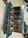
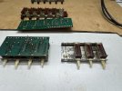
Below are some of the "ingredients", one of the -200V boards will be swapped into this unit eventually.
The redesigned board features significant thermal improvements as rott hints.

ZFe5gNr.png


img
 
This first unit is my interpretation of a reference build, with freedom to improve reliability (as to not risk K77s) and use lower noise components.
The driver boards and input filter board are near-stock with minor reliability upgrades only.

It uses 15000uF LKG Type II (same value as stock) while a future build will use 22000uF LKG Type I. These are the LKG options which fit the B-1.

Below are some of the "ingredients", one of the -200V boards will be swapped into this unit eventually.
The redesigned board features significant thermal improvements as rott hints.

ZFe5gNr.png


img
Man those boards look good. Who made them? :biggrin:

Suggestion for easier assembly:
 
BTW, I did spot a minor hick-up on those boards which "I need to report to the maker":

The ground-plane of this PCB is not there for the "electron noise" benefits but for better / more even thermal dissipation for that PCB. The ground plane extends all the way to the top with some "carve-outs" for the mounting points of the "L" shaped metal bracket. The observation is that the ground plane could have been made "smaller" not to reach underneath the metal bracket.

The reason being, the ground plane is now creating a slight uneven mounting surface so a small Nomex washer is now required for even surface mounting.
The final goal is actually to eliminate that mounting bracket and only use end mounts as the ledge of the original bracket, impedes air circulation, allowing for ~90deg C temp buildup in that area. With end-corner mounts, the slight unevenness of the PCB would be rendered inconsequential.
 
This first unit is my interpretation of a reference build, with freedom to improve reliability (as to not risk K77s) and use lower noise components.
The driver boards and input filter board are near-stock with minor reliability upgrades only.

It uses 15000uF LKG Type II (same value as stock) while a future build will use 22000uF LKG Type I. These are the LKG options which fit the B-1.

Below are some of the "ingredients", one of the -200V boards will be swapped into this unit eventually.
The redesigned board features significant thermal improvements as rott hints.

ZFe5gNr.png


img
Those boards are eye candy
 
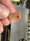
An example of a desperate attempt to resolve issues with the UC-1 (this UC-1 came from JP auction site so likely “serviced in JP):

image.jpg


Edit 7/19:
Went into this selector and what a freaking nightmare:
I need to remove the mechanical switches, clean them, then attach the new selector assembly.
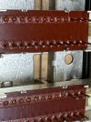
In this case, well, it looks like the prior service included cleaning and destroying the metal tabs that hold the individual switch assembly. What a freaking moron…

image.jpg

image.jpg

A nightmare
Fortunately, Yamaha used similar parts in the B-2s but that implies my work just tripled for this UC-1. :wtf:

image.jpg
 
Last edited:
Also,
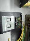
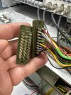
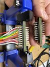
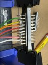
Working on a UC-1 bought from SkyFi audio. They do work on their gear. The work quality is disguising. Not the first time I rework gear from that outfit:
  • Dumb-arse moves like glue the front plate LEDs to the front plate
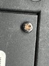
  • Mixed sheet-metal screws and machine thread screws at different locations (read destroyed the chassis screw-hole threads)
  • Soldering skills that can be better if they were done by a blind person
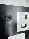
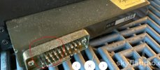
  • Not sure that they broke the pin from the pin header but now that header needs to be replaced too.
Frustrating…..

IMG_8094.jpeg

IMG_8100.jpeg
IMG_8102.jpegIMG_8101.jpeg
IMG_8098.jpeg
IMG_8095.jpeg
IMG_8092.jpeg
IMG_8091.jpeg
 
Last edited:
Fortunately the stork dropped a few of these pin headers by my place a few years back
image.jpg


Major PITA to transplant, nonetheless…
image.jpg

image.jpg
 

Attachments

  • IMG_8155.jpeg
    IMG_8155.jpeg
    95.8 KB · Views: 3
Last edited:
Also,
Working on a UC-1 bought from SkyFi audio. They do work on their gear. The work quality is disguising. Not the first time I rework gear from that outfit:
  • Dumb-arse moves like glue the front plate LEDs to the front plate
  • Mixed sheet-metal screws and machine thread screws at different locations (read destroyed the chassis screw threads)
  • Soldering skills that can be better if they were done by a blind person
  • Not sure that they broke the pin from the pin header but now that header needs to be replaced too.
Frustrating…..

View attachment 3554451

View attachment 3554444
View attachment 3554445View attachment 3554446
View attachment 3554447
View attachment 3554448
View attachment 3554449
View attachment 3554450
I personally know one of the head techs at SkyFi. He’s a stellar technician with a keen eye for detail. He also runs NovaLux Stereophonic.
I couldn’t in a million years see him leaving work like that behind. I have a feeling that amp was “played” with before SkyFi got their hands on it. If I recall correctly, they don’t service all of the gear that comes in their door, just the stuff that doesn’t pass a bench test.
 
I personally know one of the head techs at SkyFi. He’s a stellar technician with a keen eye for detail. He also runs NovaLux Stereophonic.
I couldn’t in a million years see him leaving work like that behind. I have a feeling that amp was “played” with before SkyFi got their hands on it. If I recall correctly, they don’t service all of the gear that comes in their door, just the stuff that doesn’t pass a bench test.
Possibly this one and other pieces I reworked before "just passed through" their shop :rolleyes:


A word of caution of who you vouch for…here’s my point:

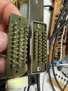
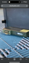
This unit, this listing: He had it open and at the very minimum, someone in that shop saw what was inside.

Listing clearly states: “fully working”. How was that possible with a broken contact pin? Yes, I get it, they moved the corresponding wire to a separate pin but that implies the matching B-1 would have had to be moded the same way. This was sold separately.....so no excuse.

IMG_8162.png
IMG_8163.png
IMG_8161.png
IMG_8159.png

note the missing pin and serial.
skycrap.JPG


Same unit within the one on my bench.
image.jpg
 
Last edited:
Man those boards look good. Who made them? :biggrin:
They do indeed! Love the main cap and clapper replacements. :trebon:

Wonderful to see how you're taking the already superb B-1 to a whole new level of excellence in reliability and sonic performance so that those magical V-FET's can live on for a least another 50 years! :thumbsup:

zaibatsu, I'll bet the inrush current on those 22000uF LKG Type I's is significant and hopefully not a problem for the primary windings of the AC line X'FMR's ... :idea:
 
a lot of B1s and their owners would say is not ;)
Good to know since the 22000's are nearly 50% more C than the design 15000's.

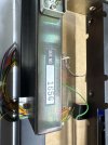
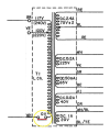
I mentioned the inrush because it looks like there's a thermal fuse link in the X'FMR. I know from experience with other amps that these can fatigue over time/inrush power cycles and 50 + years and 50% more C can be a lot of inrush ...
1752940546698.png
 
Last edited:
Good to know since the 22000's are nearly 50% more C than the design 15000's.

I mentioned the inrush because it looks like there's a thermal fuse link in the X'FMR. I know from experience with other amps that these can fatigue over time/inrush power cycles and 50 + years and 50% more C can be a lot of inrush ...
View attachment 3555102
I appreciate the concern and it is a valid concern, but you would think at the minimum, some SWAG math would have been done before spending time in redesigning this circuit :rolleyes:

The following are thoughts specific to B1 and this use case. With other amps, like Sony(s), IMMV.

First of all, the primary winding THERMAL fuse would be triggered likely at temperatures above 100c..or more. Let's not mix things up in here. You are much more likely to see that fuse go bad for keeping that B-1 at idle in a shelve cabinet with increased unnecessary thermal exposure due to poor ventilation for a long time (sustained baking of those transformers).

But YES, The primary winding of the transformer (not the thermal fuse) would be a valid concern if it was undersized, or if the increase of inrush current would be substantially greater. "Greater" in my book would be few times that of the original design, and here's why I am not concerned at all with this use case:

The original main PSU capacitor bank per channel consists of 2 × 15,000 µF electrolytic capacitors. Due to part availability, these are replaced with 2 × 22,000 µF capacitors, increasing the bulk capacitance by ~46%.
While the 46% increase in capacitance theoretically increases inrush current magnitude and duration, the thermal fuse:
  • Is not a current-limiting component
  • Does not react to millisecond-scale transients
  • Is designed to withstand power-on surges that are part of normal transformer operation
Additionally, older electrolytic capacitors often had wide positive tolerance bands (e.g., –10% to +50%, sometimes up to +100%), meaning the original 15,000 µF parts may have operated effectively near or above 20,000 µF when new — narrowing the practical delta compared to the modern replacements.

Therefore, the primary stress point from increased inrush is borne by the external mains fuse, not the thermal fuse. As long as the external slow-blow fuse remains in place and no faults exist in the rectifier circuit, the transformer thermal fuse is highly unlikely to be affected under normal operating conditions.

A separate concern would be stressing the original rectifier, but that is not applicable here.

If you intend to upgrade your amp and can only find 22,000uf caps and still have hesitations, I think an NTC inrush current limiter would actually work with the B-1.

 
Excellent explanation as always Pete.

:thumbsup:

For about the millionth time saying this, I need to get back to mine !!! :whip:
 
I appreciate the concern and it is a valid concern, but you would think at the minimum, some SWAG math would have been done before spending time in redesigning this circuit :rolleyes:

Yes indeed! Having worked as part of an engineering team for 30+ years though, I'd rather deal with an actual inrush current measurement with the highest 22,000uF's I could find to be comfortable with them in my B-1 rather than SWAG math which is good to establish a ROM as you've clearly demonstrated. :thumbsup:

That said, in the end the whole question is totally academic for me because I'm completely happy with my non 22,000uF recon'd B-1 version ... :music:

1753030364475.png

:biggrin:
 
Yes indeed! Having worked as part of an engineering team for 30+ years though, I'd rather deal with an actual inrush current measurement with the highest 22,000uF's I could find to be comfortable with them in my B-1 rather than SWAG math which is good to establish a ROM as you've clearly demonstrated. :thumbsup:

That said, in the end the whole question is totally academic for me because I'm completely happy with my non 22,000uF recon'd B-1 version ... :music:

View attachment 3555955

:biggrin:
and the actual inrush current would be just as relevant as the SWAG above, .....unless of course, you would know the core size or wire size (preferably both) of that transformer. But I think you know that already since you spend so much time around engineers and you likely also know that the delta of inrush current, in this case, is relatively negligible.

Nothing wrong with the original 15,000uf. If more would be available, I would use them in my own unit in a hearth beat. Nothing wrong with using the 22,000uf instead either. Using the right type of capacitor here is likely to bring in more benefits than the relative variance in capacitance in this case. Also very important is addressing a few other shortcomings such as how the CT of the transformer is managed, the type of rectifier used, etc.

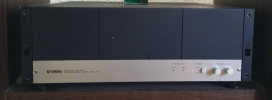
That B-1 looks mighty nice. I just hope the shelve above does not impede proper airflow and to weaken those thermal fuses inside the transformers ;).
 
Back
Top Bottom