• The move to the new server is done. There are some software and database maintenance updates in process. This has us passing the hat around to help out. We appreciate any donations. Seriously, even a dollar helps. The payment page may be found here - https://www.audiokarma.org/support.html

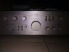
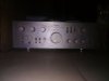
This TRIO-KA 9900 has been sleeping for 10 years! Let's wake her up!!

KA907nKA9900

Active Member
Lost the right channel in January 2010.

I was so traumatized, I just stopped using it. I wanted access to all the power or none at all.

I have never listened to anything that sounded half as good.

So I put it in storage pending when I could restore it.

Then I bought a KA-907 that turned out to be a turd and so I could not use it as a reference for restoring the KA-9900

I even purchased service manuals and considered shipping it to known names on this forum to repair but held back due to the cost

Then life happened and I didn't until now.

Now I need all the help in the world to get her back online.

This is a brief introduction.

Will provide additional details in subsequent posts.

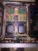
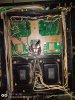
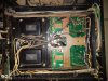
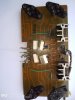
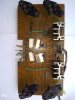
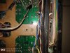
Sorry about the picture quality. Will do better in subsequent pictures

Counting on your collective xperience to bring this back to life
 

Attachments
  • IMG_20200506_070353.jpg
    IMG_20200506_070353.jpg
    47 KB · Views: 95
  • IMG_20200506_070501.jpg
    IMG_20200506_070501.jpg
    51.7 KB · Views: 92
Last edited:
Register to hide this ad
Most Excellent, your very own thread about your amp to let folks drop in and lend a hand.

A missing channel can frequently be found in the controls. Lost because the absolute smallest contamination, like smoke, dust, grime and such is one Million Times Larger than an electron and electrons are not going to find their way around the blockage, so we clean the controls and hope for the best.

Here is a thread about cleaning controls. https://www.audiokarma.org/forums/i...diots-guide-to-using-deoxit-revisited.207005/ something I would do to the 9900.

Do you know that the 9900 has had electrical failure or is it just a lost channel? If it is an electrical failure, you want to build a dim bulb tester and use it to power the unit to avoid any further damage. google or search ak gets DBT info.

Let us know how you make out with this and we can find folks the help you go further until we find the issues.
 
Last edited:
Sounds like my KA-80.

Make a dim bulb tester and use it. The lamp filament should glow brightly for a couple seconds as the main filter caps charge, then drop to a dim glow (how dim depends on the state of the amp and the wattage of the bulb -- a low wattage bulb will be brighter).

If the filament dims down nicely, you don't have a short. If it stays bright, you will need to dig in and find out what failed. Check offset voltage and bias as those will tell you if you have serious problems in that dead channel (high offset/high bias and no sound is a shorted transistor most likely).

Next step is to clean all the contacts and switches with DeOxit. All it takes to drop a channel is a dirty contact in the speaker switch after all. Ditto for tape monitor or selector switches -- the Sansui I bought my Mom 40 years ago has a flaky phono selector switch, tends to drop the right channel out completely. Do not use DeOxit on the speaker protection relay, it's better to remove the plastic cover and put a slip of high quality paper (if such a think still exists, rag or linen paper is best), gently hold the relay contact closed, and pull the slip out. This should remove any dirt or corrosion in a pass to three. You do NOT want residue on those contacts, it will inevitably char and cause trouble. The relay may need to be replaced, the contacts can pit beyond cleaning.

If that doesn't help, it's time to fire it up on the dim bulb tester and start checking voltages per the schematic or parts layout -- Kenwood service manuals are pretty good for that information. When you find a voltage that isn't right, start looking for the dead part(s) that could cause the problem. USE SHIELDED PROBES! Last thing you want to do is short something with a long, bare probe and blow out expensive parts.

If the protection relay closes and you have no sound and no smoke from overheated circuits, likely it's a dirty contact or an open or shorted transistor. That will show up in the voltage checks.
 
Most Excellent, your very own thread about your amp to let folks drop in and lend a hand.

A missing channel can frequently be found in the controls. Lost because the absolute smallest contamination, like smoke, dust, grime and such is one Million Times Larger than an electron and electrons are not going to find their way around the blockage, so we clean the controls and hope for the best.

Here is a thread about cleaning controls. https://www.audiokarma.org/forums/i...diots-guide-to-using-deoxit-revisited.207005/ something I would do to the 9900.

Do you know that the 9900 has had electrical failure or is it just a lost channel? If it is an electrical failure, you want to build a dim bulb tester and use it to power the unit to avoid any further damage. google or search ak gets DBT info.

Let us know how you make out with this and we can find folks the help you go further until we find the issues.

Thanks for your deep drive into likely causes.

Someday I was quietly enjoying the unit, when a friend decided to charge her phone with the same power strip as the unit was connected it, when suddenly the unit stopped playing as before the lights in the room dimmed and I discovered the right channel was gone.

I did contact a tech to help me fix it, but the right channel soon went out again.

I think the problem is electrical, here is why, the tech that worked on it isolated the right channel entirely when I took the unit to him a second time. I took apart the unit and observed the Q2 transistor was shaking, the R4 resistor looked burnt and D2 diode was replaced on the Power Amp PCB Assembly board marked ELNA-F45 94V-0/ J25-1603-04/X07-1670-10.

I just cleaned it up. Once the board is dry, will update this post with pictures.

That notwithstanding, I will add Deoxit to my shopping list and build a dim bulb tester.

Thanks again for the standby offer of help.

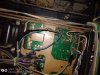
I will provide one picture right away, the unit is upside down and the red circles are where the right was isolated.

As at the time the unit was stored away, the left channel was still functional, but the power transistors were not all original. I will provide details about those in a separate post.
 

Attachments

  • IMG_20200613_195542 (2).jpg
    IMG_20200613_195542 (2).jpg
    111.5 KB · Views: 65
  • IMG_20200613_195542 (2).jpg
    IMG_20200613_195542 (2).jpg
    111.5 KB · Views: 59
  • IMG_20200613_195756 (2).jpg
    IMG_20200613_195756 (2).jpg
    131.8 KB · Views: 57
  • IMG_20200613_203027 (2).jpg
    IMG_20200613_203027 (2).jpg
    163.2 KB · Views: 64
  • IMG_20200613_203049 (2).jpg
    IMG_20200613_203049 (2).jpg
    164.1 KB · Views: 58
Last edited:
Sounds like my KA-80.

Make a dim bulb tester and use it. The lamp filament should glow brightly for a couple seconds as the main filter caps charge, then drop to a dim glow (how dim depends on the state of the amp and the wattage of the bulb -- a low wattage bulb will be brighter).

If the filament dims down nicely, you don't have a short. If it stays bright, you will need to dig in and find out what failed. Check offset voltage and bias as those will tell you if you have serious problems in that dead channel (high offset/high bias and no sound is a shorted transistor most likely).

Next step is to clean all the contacts and switches with DeOxit. All it takes to drop a channel is a dirty contact in the speaker switch after all. Ditto for tape monitor or selector switches -- the Sansui I bought my Mom 40 years ago has a flaky phono selector switch, tends to drop the right channel out completely. Do not use DeOxit on the speaker protection relay, it's better to remove the plastic cover and put a slip of high quality paper (if such a think still exists, rag or linen paper is best), gently hold the relay contact closed, and pull the slip out. This should remove any dirt or corrosion in a pass to three. You do NOT want residue on those contacts, it will inevitably char and cause trouble. The relay may need to be replaced, the contacts can pit beyond cleaning.

If that doesn't help, it's time to fire it up on the dim bulb tester and start checking voltages per the schematic or parts layout -- Kenwood service manuals are pretty good for that information. When you find a voltage that isn't right, start looking for the dead part(s) that could cause the problem. USE SHIELDED PROBES! Last thing you want to do is short something with a long, bare probe and blow out expensive parts.

If the protection relay closes and you have no sound and no smoke from overheated circuits, likely it's a dirty contact or an open or shorted transistor. That will show up in the voltage checks.
For both of you to mention the dim bulb tester and DeOxit, it is pretty much clear those are must haves.

Thanks for the treatise on their use and how they work. Very much appreciated.

I have provided a greater level of detail in the post above as to the problem I think the unit has.

I do have a service manual so that is certainly be a plus.

It seems that this forum has ideas for making changes to the unit to make it bulletproof and that is one of the reasons why I had to finally sign up
 
Well, first you are going to have to "un-butcher" the mess your technician made in "isolating" the right channel. It's already isolated by design, has a separate transformer, etc.

The best solution is to return it to original condition, a hack job with taped wires all over is NOT a good thing, especially if those splices are not fully soldered.
 
Well, first you are going to have to "un-butcher" the mess your technician made in "isolating" the right channel. It's already isolated by design, has a separate transformer, etc.

The best solution is to return it to original condition, a hack job with taped wires all over is NOT a good thing, especially if those splices are not fully soldered.

Tell me how to address those taped wires. What is best practice?

That's why I am here. I took an online automotive electronics troubleshooting course, the principles of electronics don't change with the application, I belief with the help of this forum, and that background, I would do a better job of getting it back in shape.

One challenge is that I would have to import all the components I need.

So I would prefer to have a full shopping list before ordering.
 
Undo one taped connection at a time and evaluate what you have. If this is just a single conductor, install heat shrink tubing on the wire and make a clean solder joint in the wire and cover with the heat shrink and shrink it.

If there are two conductors, like speaker wire under the tape do each conductor separately as above.

Don't take off more pieces of tape than you can keep track of the wires underneath is the reason I would do one at a time.
 
Undo one taped connection at a time and evaluate what you have. If this is just a single conductor, install heat shrink tubing on the wire and make a clean solder joint in the wire and cover with the heat shrink and shrink it.

If there are two conductors, like speaker wire under the tape do each conductor separately as above.

Don't take off more pieces of tape than you can keep track of the wires underneath is the reason I would do one at a time.
All of them are single wires that were cut and then rejoined. So all I need to do is clean solder joints, install heat shrink and shrink for each joint
 
Let's take a look at the Power Amp PCB Assembly board marked ELNA-F45 94V-0/ J25-1603-04/X07-1670-10.

I am no fan of splicing or cutting wires if that can be avoided.

I wasn't the one who cannibalized the wires that connect this board to the amp, I wonder why instead of disconnecting it properly, he had to do that, but that is in the past now.

I forgot to add that diode D1 was also replaced.

There is also evidence of bad soldering if you look at the board carefully.

Any recommendations on soldering irons that would not break the bank?
 

Attachments

  • IMG_20200614_135845 (2).jpg
    IMG_20200614_135845 (2).jpg
    68.7 KB · Views: 37
  • IMG_20200614_135825 (2).jpg
    IMG_20200614_135825 (2).jpg
    109.4 KB · Views: 40
  • IMG_20200614_135835 (2).jpg
    IMG_20200614_135835 (2).jpg
    53.3 KB · Views: 35
  • IMG_20200614_135905 (2).jpg
    IMG_20200614_135905 (2).jpg
    112.1 KB · Views: 37
If you can afford one, a temperature regulated "soldering station" is by far better. Availability may be an issue for you, even though they are all made in China.....

Very much better than a standard soldering iron as you can adjust the temperature at the tip.

You should also get a solder remover (the cheap kind with a suction bulb will work well for a few projects). If you want to do this for a business you need a power version.

It is far better to un-solder the pins than to cut the wires to those boards. Wire is usually solid core copper, and will not tolerate much bending. Using a solder sucker you can easily free the pin with wire wrap from the board.

You will also need a good digital volt meter.
 
If you can afford one, a temperature regulated "soldering station" is by far better. Availability may be an issue for you, even though they are all made in China.....

Very much better than a standard soldering iron as you can adjust the temperature at the tip.

You should also get a solder remover (the cheap kind with a suction bulb will work well for a few projects). If you want to do this for a business you need a power version.

It is far better to un-solder the pins than to cut the wires to those boards. Wire is usually solid core copper, and will not tolerate much bending. Using a solder sucker you can easily free the pin with wire wrap from the board.

You will also need a good digital volt meter.
Shopping list
1. temperature regulated soldering station
2. solder remover, any pictures, is this example from amazon good enough? https://www.amazon.com/WEmake-WM-SP4-Solder-Sucker-desoldering/dp/B0002KRAAG

About the shopping, if it is on eBayUS or AmazonUS, that will be just perfect for me

I have a pretty good DMM, not a Fluke but good enough to get by
 
First think how much buying all these tools will cost you, then weigh up how much taking it to a reputable tech will cost.

Chem-wik desoldering braid is the only thing I use on vintage amplifiers, especially those which have already been worked on 2mm should do the trick. Desoldering pumps? I use those on output transistor pads where the board can take some punishment.

Solder stations? Look on ebay for a good used Weller or metcal. Dont forget tips.
 
With the wires they look straight from the transformer, look for the specs of the wire on them, should say something like 18awg and have a code on them beginning UL.

Also unwrap the tape and take clear close up photos and post them here.
 
First think how much buying all these tools will cost you, then weigh up how much taking it to a reputable tech will cost.

Chem-wik desoldering braid is the only thing I use on vintage amplifiers, especially those which have already been worked on 2mm should do the trick. Desoldering pumps? I use those on output transistor pads where the board can take some punishment.

Solder stations? Look on ebay for a good used Weller or metcal. Dont forget tips.

If we had those kinds of techs, I would be glad.

I want to believe we do.

But even if we have, the problem is, I don't know how or where to find them. It is easier to find a reputable tech in the US or Europe than it is to find locally, because the local techs as a general rule do not have an online presence.

That said, I am in this for the long haul. So provided the costs are affordable, I will most definitely buy or plan to buy.

Thanks for the hint with respect to Chem-wik desoldering.
 
Last edited:
  • Like
Reactions: trs
With the wires they look straight from the transformer, look for the specs of the wire on them, should say something like 18awg and have a code on them beginning UL.

Also unwrap the tape and take clear close up photos and post them here.

I have attached pictures of the wires, those are the original wires, they were cut by the tech who worked on the amp. Other than those cuts and the tapes, nothing has changed from its factory state (specifically referring to the view of the underneath)
 

Attachments

  • IMG_20200614_212806 (2).jpg
    IMG_20200614_212806 (2).jpg
    133.4 KB · Views: 27
  • IMG_20200614_212916 (2).jpg
    IMG_20200614_212916 (2).jpg
    151.2 KB · Views: 25
  • IMG_20200614_213014 (2).jpg
    IMG_20200614_213014 (2).jpg
    148.1 KB · Views: 24
  • IMG_20200614_213041 (2).jpg
    IMG_20200614_213041 (2).jpg
    141.4 KB · Views: 24
  • IMG_20200614_213051 (2).jpg
    IMG_20200614_213051 (2).jpg
    116.6 KB · Views: 27
Last edited:
So let's take a look at the power transistors and the readings I took to determine the good from the bad
 

Attachments

  • IMG_20200614_140049 (2).jpg
    IMG_20200614_140049 (2).jpg
    45.4 KB · Views: 23
  • IMG_20200614_140121 (2).jpg
    IMG_20200614_140121 (2).jpg
    37.4 KB · Views: 25
  • IMG_20200614_140141 (2).jpg
    IMG_20200614_140141 (2).jpg
    34.6 KB · Views: 25
  • IMG_20200614_140145 (2).jpg
    IMG_20200614_140145 (2).jpg
    47.2 KB · Views: 25
  • IMG_20200614_140151 (2).jpg
    IMG_20200614_140151 (2).jpg
    53.2 KB · Views: 25
  • IMG_20200614_140205 (2).jpg
    IMG_20200614_140205 (2).jpg
    36.9 KB · Views: 24
  • IMG_20200614_140220 (2).jpg
    IMG_20200614_140220 (2).jpg
    33.3 KB · Views: 23
  • IMG_20200614_140229 (2).jpg
    IMG_20200614_140229 (2).jpg
    45.6 KB · Views: 25
  • IMG_20200614_140244 (2).jpg
    IMG_20200614_140244 (2).jpg
    42.1 KB · Views: 23
  • IMG_20200614_140306 (2).jpg
    IMG_20200614_140306 (2).jpg
    39.7 KB · Views: 25
Back
Top Bottom