• The move to the new server is done. There are some software and database maintenance updates in process. This has us passing the hat around to help out. We appreciate any donations. Seriously, even a dollar helps. The payment page may be found here - https://www.audiokarma.org/support.html

Thoughts on restoring a Dynaco ST70

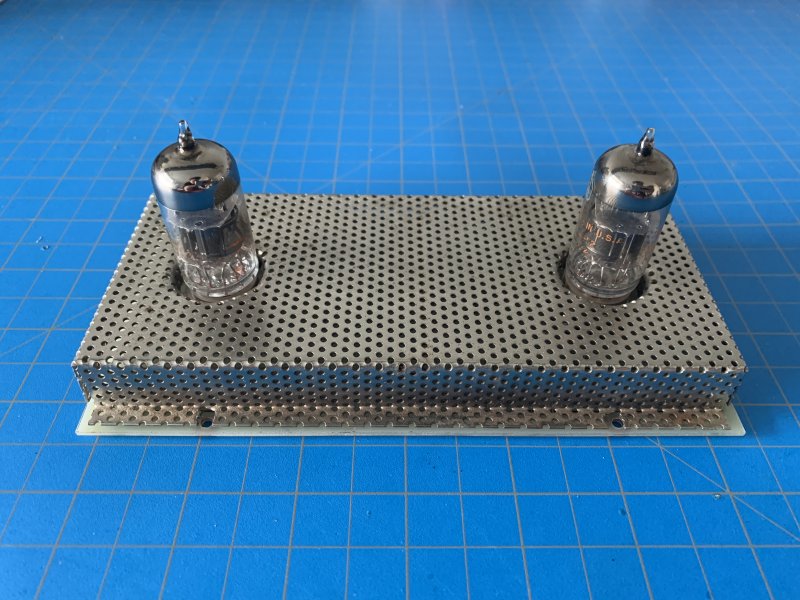
Alright, first hiccup. My st70 came with this nifty screen that fits over the PC board. But it will not fit the replacement board from dynakitparts. It seems the position of the tube sockets is about 1/4" wider that the original on each side. It makes me sad because the screen is really nicely made, perforated stainless and nicely bent. Definitely not shoddy craftsmanship making that. It looks like I'll have to replace it if I want to use the replacement board but dang it the shop isn't well set for sheet metal fab' and milling it on the Haas milling center will probably make even less sense.

I made a complaint last year to Dynakitparts about their replacement boards not working with the OEM cover. He even told me that they were aware of it, but due to several dimension differences between boards a compromise was needed somewhere. I asked him why don't you put that info on the website so people who have and want to use the OEM cover will know about it. He said it was a good idea, but they still haven't. I would think when making compromises they would make the tube socket location high, since there is an OEM cover which depends on it. Unfortunately you and I are both unable to use this cover any longer which was one of the unique things about a factory wired ST-70.

Bill
 
The disappointment here is understandable. But FWIW not all factory wired Stereo 70s came with the PCB cover.
I've always heard they did, I guess Bob Latino thinks they did also. https://dynacotubeaudio.forumotion....ween-factory-wired-and-kit-built-st-70-photos "Dimensionally accurate to the original specifications for a “drop-in” trouble free installation. Our board design will accept either the original or new production components as available from Dyankit." I'm just glad they didn't take the same tact with mounting holes.
 
Thanks for the information it's really helpful! That's really disappointing that they are well aware the replacement board will not properly fit some factory wired st-70s but they won't say a word about it. I had crazy busy days at work but in the little time I had, I drew up the schematic and (initially) copied the part placement of the original board. It feels like routing for the 6GH8A tube is a little awkward compared to the 7199s but if I route for double sided boards, it's a snap. This btw is what dynakitparts did too, so I can't say that I'm buying that they had to compromise between tube placement and routing possibility. Specially that the board is pretty large and has tons of breathing room for 1-1.2mm traces. After looking at the routing, I decided to go a little off-script and moved a couple resistors and placement of wirepads to let the traces breath. This also made it so that I could easily route for a single layer board. Next is etching and silkscreen printing. I decided against sending it to a small PCB shop to keep alive the spirit of DIY'ing in this tube amp. So everything will be made in house.
 
Very impressive of you to design and fab your own board. Me, I've just surrendered, I'm not buying, repopulating, removing and reinstalling another CCA at this point.
 
Thank you, well to be honest I'm so close to just repopulate the original board. I got pretty much 100% success removing the old solder with the vacuum soldering station and reflowing the solder joints. There was just one point that delaminated a little but that's an easy fix; a little epoxy and it's all set, oldest trick for rework.

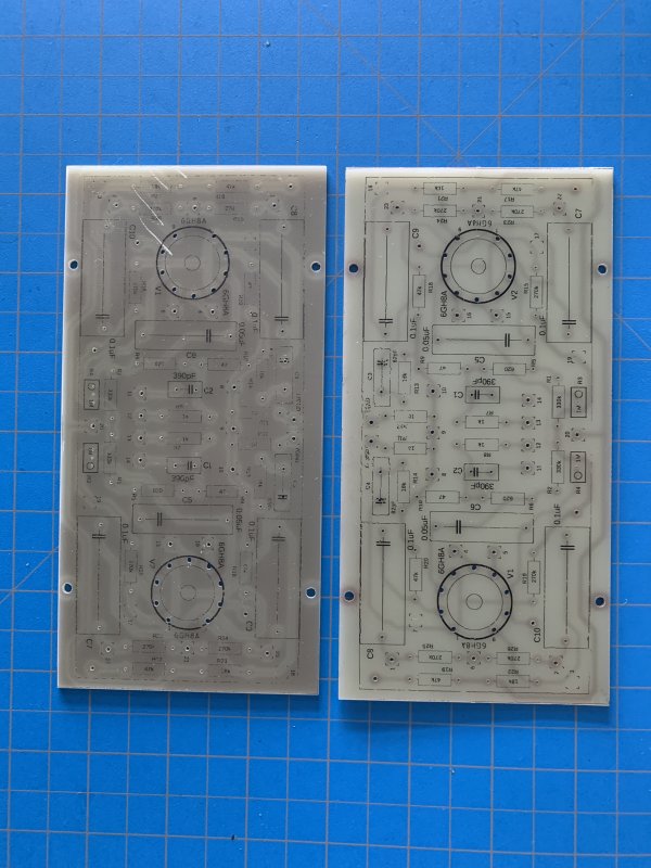
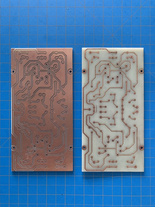
In the meanwhile I got two boards made, one with just trace isolation and the other with bare traces. I'm still not sure which one I'll end up using; the plan for the trace isolation was to use the unconnected plane as a ground plane. It has plenty of clearance for 600V and adds the benefit of screening. The bare trace one looks more familiar though and it has no chance to arc. I'm attaching a picture of the screen too to see the fitment. As you'd expec, the silkscreen printing is a hit or miss, but that's something that happens when you print at home. If the OCD kicks in, I'll just wipe it off with strong acetone and try a couple more times.

 
Thank you, well to be honest I'm so close to just repopulate the original board. I got pretty much 100% success removing the old solder with the vacuum soldering station and reflowing the solder joints. There was just one point that delaminated a little but that's an easy fix; a little epoxy and it's all set, oldest trick for rework.

In the meanwhile I got two boards made, one with just trace isolation and the other with bare traces. I'm still not sure which one I'll end up using; the plan for the trace isolation was to use the unconnected plane as a ground plane. It has plenty of clearance for 600V and adds the benefit of screening. The bare trace one looks more familiar though and it has no chance to arc. I'm attaching a picture of the screen too to see the fitment. As you'd expec, the silkscreen printing is a hit or miss, but that's something that happens when you print at home. If the OCD kicks in, I'll just wipe it off with strong acetone and try a couple more times.


Wow they look very well made, I'm very impressed with how they both turned out. Put one in now and report back on how it performs for you. Didn’t take notice, are these for original tube or the sub?

Bill
 
Thanks! That's a good idea, the board is very easy to swap out. For now I'll stick with the triode/pentode combo tube but from what I've been reading (and makes more sense to me too) it's a better idea to use separate triode and pentode tubes and that way you have more variety for tube rolling.

I made these boards directly for the replacement 6GH8A tubes. Last time I checked there were too few 7199 listings and none of them were for a matched pair either. From what I understood, these triode/pentode tubes are a PITA to match. Not sure if the 6GH8s will perform as good as the 7199 because there are conflicting opinions on this one. I wouldn't know either because when I first got the amp, one of the 7199 was so noisy I couldn't really appreciate it. But I'll try with the other one that seemed to be good. When time comes I'll make an adapter from 6gh8 to 7199 and compare the L/R channel and listen to see if there's really any noticeable difference to my ears.
 
Wouldn't at least the pentode need to be close between the two tubes so that the driver stage on L/R has the same gain?
 
Oh yes, forgot to mention. I replaced the 1.5M resistor in the layout with the footprint of a trimmer pot. Found a good one from bourns that is rated at 500V so it should hold up fine. Thanks for the references, it really helped me understand what that resistor does and how it affects the phase inverter down the line. Initially I put provisions for a resistor in series with a trimmer put to be able to make very fine adjustments in the range of 800k like you suggested. But then again the trimmer has 25 turns for the entire range so I abandoned that idea and just have the trimmer alone.
 
Well the driver board is populated and awaiting the rest if the amp to get in shape. I measured the original capacitors in the bias supply and one of them is scary how bad it is. The other surprise was the dual ceramic cap. Ceramics tent to last a while before needing replacement but these are just terrible.
AF03E533-CE9C-4ED6-AD30-E9085406EF6C.jpeg
 
Well the driver board is populated and awaiting the rest if the amp to get in shape. I measured the original capacitors in the bias supply and one of them is scary how bad it is. The other surprise was the dual ceramic cap. Ceramics tent to last a while before needing replacement but these are just terrible.
View attachment 2016013
It's just a bypass/reservoir for the floating heaters, noncritical.
 
Wellp, I put together everything and the driver board works well. "Tiny" oversight on my end, on one channel in the layout I didn't pay close enough attention to matching the phase and out-of-phase connections to the respective power tubes. Ups! :eek: Luckily I caught in time and didn't cause any damage whatsoever. So far I only played it on dummy loads and signal generator. The scope shows a really clean signal but I'll soon play it on a set of sacrificial speakers. Just need to get those 1M trimmer pots adjusted, do one last check and button it up.

On a side note, I was expecting that line voltage will not be enough for this amp but it takes about 1.5-1.7V to drive this thing to full power. Is this normal or it's just me having really low gain in the driver stage?
 
Last edited:
Alright so next stop, I need to make a line stage. And down the [audio DIY] rabbit hole I go again :D
Ok so this was the original plan: Let's have a tube kit for playing records. I already made an extremely fine quality phono stage which outputs around 700m, was thinking to put a potentiometer in between and boom. Looks like I'll need a line stage as well. Something with a selectable 2-4 gain should do it. But that's for another day, let's finish up the ST-70 first.
 
I've found the FX 01 Tube to be a decent no-frills line stage, needing only an input selector, for $31.
It does invert acoustic polarity, so reverse polarity of speakers.
 
@Pio1980 can you confirm with me the adjustment for the G2 trimmer? So I'm first measuring the available B+ on the triode which is taken between the top end of the plate 47k resistor to the bottom end of the cathode 47k resistor. Then I adjust the penthode's G2 trimmer so that the voltage across the triode's cathode resistor to be 25% of that B+ we measured earlier.
Did I get it right?
 
I asked Dave and Steve this very question myself and according to his response your understanding and description sounds correct, you want full B+ as it comes from power supply, so ground to power supply B+, then adjust for 25% as measured across cathode resister.
 
Last edited:
Back
Top Bottom