• The move to the new server is done. There are some software and database maintenance updates in process. This has us passing the hat around to help out. We appreciate any donations. Seriously, even a dollar helps. The payment page may be found here - https://www.audiokarma.org/support.html

Thoughts on restoring a Dynaco ST70

radu_c

New Member
Hi everyone, I recently came in possession of an ST70 factory wired, all original components. Other than a hum in one of the channels that I traced to the 7199 tube on one side, it's fully functional.

I'm very comfortable around electronics but I am relatively new to tubes. I want to ask you all what would be a good (sensible) restoration plan for it? I can't say that I'm keen on using completely different topologies for the PC board I saw on other sites, or do radical modifications to it because... well then, is it an ST70 anymore?!

Obviously I'll change out the capacitors, and since we're here, it was recommended on other sites to use the 80/40/30/20 at 600V from dynakitparts, instead of the stock 30/20/20/20. Is this wise? I was looking at the datasheet for the GZ-34 rectifier tube and there it says the maximum capacitance should be 60uF.

What else... I'll change out the selenium diode to replace it with a current silicone one, since I heard it's not too good on the health if it goes out.

So to sum it up, what PC board would be good for a sensible restoration considering the 7199 tube is extinct and, is the 80/40/30/20 multi-section capacitor a good idea for the model of rectifier tube in this thing?

Thanks in advance.

Radu,
 
Register to hide this ad
I think the cap from dynakitpars wil use the 20uF as the first cap, thus keeping the GZ34 happy.
( you choose yourself how to connect the cap)

As for the 7199 ; you van get a new one for a lot of money. Or you could get one or two
adepters and a couple of EFC80 and replace both 7199 on your amp. This combo is
a good replcement and will in a foreseeable future ( say 30 years) be a sustaninable
alternative to 7199.

A more expensive is to get a new board that has been rerouted for ecf80/ecf82 AND a couple of tubes,
a little more expensive then the previous and still sustainable for the closest 30 years.

My recommendation is to keep the original board, get 2 adapters and 2 7199 replecement
( 6u8 / 6bk8 / ECF80 / ecf82 ) and a new can cap from dynakitparts.
 
The new, larger cap is OK but keep to no larger than 40uf for the first cap off the rectifier. I think the usual setup is rectifier -> 40 -> choke -> 80 -> 30 -> 20
 
IMO, with a different driver topology or other big changes it would no longer be a Dynaco.


Order of installation is 40/80/30/20 thereby keeping the amount of capacitance the tube rectifier sees within spec. I believe dynakitparts.com might provide a diagram for the wiring. Current production Gold Lion GZ34 are said to be a good choice without having to spend big $ for an old stock tube.


Try a UF4007 diode for the bias supply. The two electrolytics in the bias supply should be changed to 100µF @100VDC each. Reason is the diode change and potentially higher value of AC mains pushes the voltage on those two electrolytics up against the original 75VDC rating. Increasing the capacitance from 50µF to 100µF has been demonstrated to reduce ripple in the bias supply.

If the pads and traces on the original PC board are delaminating to the point that the board is no longer usable, then exact copies with the original circuit topology are available. dynakitparts.com has two versions. They both use the original Dynaco circuit topology, with one using 7199 while the other substitutes 6GH8A or 6U8 for the 7199. Also, a plug-in adapter is available from dynakitparts.com that allows the use of 6GH8A or 6U8 in the 7199 board. Scroll down here: https://www.dynakitparts.com/product-category/dynakit-products/pc-boards/

Refreshing all the solder joints throughout the amp could yield an improvement Someone in another forum reported a significant sonic improvement after he refreshed all the solder joints in his old PAS preamp.

If you don't already have them, here are two documents that are "must reads:"
https://www.dynakitparts.com/wp-content/uploads/Dyna-ST70.pdf
http://www.audioregenesis.com/documents/ST-70 Base Line Testing.pdf

The original owners manual has a list of reference voltage values on the page with the power supply schematic. I'd suggest taking readings in your amp at the indicated nodes and see how your readings compare to the standard values in the manual. I'd also get something like the Kill A Watt device to conveniently monitor your AC mains value 24/7 http://www.p3international.com/products/p4400.html
I would go for a board from Dynakit for an original Dynaco. New board made from better materials, new componants and the use of a more plentiful and cheaper tube type. Using one of the 3 or 4 tube boards would turn it into something else.
 
I did my ST-70 last year and went with the 80/40/30/20 can and a replacement board from Dynakit. Don’t make the mistake I made and put that can in without following the directions. Just don’t.
After experimenting with driver tubes, I settled on RCA 6GH8As and adapters. I was able to match up a nice pair for little money compared to the 7199s and the amp sounds really great. I should have just bought the 6GH8A circuit board.
It was good in 1959 and it’s likely better now with better parts so I’m happy with the stock circuit.
Change out the SE rectifier in the bias circuit and replace those caps.
I also recommend the ‘yellow sheet’ mod to protect the rectifier tube.
 
Absolutely check that mains voltage and use a transformer to bring it down, if necessary.
Peter, do you think the yellow sheet mod would affect the sonics in the stock amp? I didn’t notice any difference, but wasn’t listening for it either.
 
with a tube in series I doubt it would. The tube is effectively a resistor ahead of a cap, so you get an RC low pass filter ahead of the amp circuitry. Straight solid state power supply maybe some switching noise could get through if the filter caps are not in good shape. Bypass the first one with a small film and that mostly becomes a non-issue.

The really critical thing for solid state diodes in tube equipment is high enough PIV ratings to be effective. The 4007 series diodes are only good for 1kv PIV, the rectifier tube is good for something like 1500. ST-70 is 375-0-375 on the transformer, or 750vac rms end to end. The peak voltage is 1050 volts, slightly beyond what the usually suggested diodes are actually rated to handle. A pair of diodes in series or a diode with a 1.5kv PIV rating is a much more sensible choice, especially if the idea is to protect the tube from excessive PIV.
 
Thanks all for your suggestions. It totally makes sense what I'm reading here. About the multi-section capacitor I assumed (stupidly) that the 80uF section is the capacitor the rectifier tube is seeing directly. I read into it a little more and just like @peterh, @petercapo and @gadget73 mentioned, the capacitor should be used as rectifier->40->choke->80->30->20. Sorry about that guys, should've done my homework better but all in all, it's good to get confirmation from multiple sources.

The original circuit board looks pretty good (at room temp) but I'm sure if I put some heat to it to replace the signal path and grid leak capacitors the traces will probably start to delaminate. It seems this amp did not ran much... But either way, I'll go ahead with a new PCB from dynakitparts since it also looks original. Am I right in saying it's the same backing material for these new PCBs as the original ones? They say on their website that the new PCBs are made from polyamide. Or were the original PCBs made of bakelite, I forget. Not that it matters, I only care about function and longevity.

For the bias supply diode, I plan to use an ultra-fast diode shunted by a small ceramic cap. I learned this trick at work with our experimental designs. It tends to produce a much cleaner DC signal and only very high harmonics are getting through. But then again, looking at the schematic, do I really need to have that clean of a signal in a bias circuit?! My guess is probably not.
 
About the yellow sheet mod. I get that it helps the rectifier tube with the reverse current (because there will be none :-D ) but I keep reading that it helps with the sound quality. I got to ask because it doesn't make much sense to me how that would work. The only time the rectifier tube is in conductance is during forward voltage where it has the characteristic sag under load. But the reverse voltage will just suppress the current so if there are solid state diodes ahead of the tube, it shouldn't make any difference in the signal coming out of the tube right? or am I missing something?
 
new ones are probably fiberglass I expect, the old ones were phenolic similar to Bakelite. The bigger problem with the old ones is the traces are prone to lifting if you aren't real careful. I've fixed old boards, its possible with care but if you're working with one that is well baked and damaged from prior work it gets annoying very quickly.

the diodes don't affect what the tube does, the idea is that they provide some PIV protection in the event of a tube failure. Supposed to make life for the rectifier a little nicer is all. The ST-70 is a bit hard on the rectifier current-wise.
 
Woop, just did a test to see how the board deals with the heat and as I was fiddling with a pin, the trace lifted up ever so gently like a Swan Lake ballerina :-D Alright, new PCB it is. Actually, before that let me break out the solder sucking station and see if that does a better job.
 
1F3891AC-3855-4B7F-B416-28C1729B5868.jpeg The new board looks similar to the original but probably look like a potato chip after 50 years.
I returned to the yellow caps that were included in the kit and think the amp sounds better than it did with the Orange Drops.
My recommendation is to get the 6GH8A board unless you have a stash of 7199s.
 
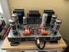
Nice looking amp you got there! The new board does look exactly like the old one. Unfortunately I don't have 7199s other than the ones that came with the amplifier and even those don't seem to be performing too well. I'll go directly to the revision B board with the pinout for a 6GH8A. I'll start another thread if there isn't one already about how the 7199 equivalents sound like.

Oh interesting, I was thinking to go exactly with the orange drop caps. I know it's subjective so I wouldn't touch the subject of coupling capacitors. Did you use the 716 or 715 series?
 
I can't say that I'm keen on using completely different topologies for the PC board I saw on other sites, or do radical modifications to it because... well then, is it an ST70 anymore?

Just in the spirit of friendly observation: modifying Stereo 70s was a great passion for audio amateurs during the 1970s and 1980s into the 1990s before single ended triodes became the new passion in the late 1990s. So one could very well state that modifying a ST70 is absolutely "in the tradition" of being an audio hobbyist with its roots going back almost 50 years. For many audio enthusiasts, it was an opportunity to put to practical use what they had learned about electronic circuit theory in high school. It inspired me to pursue electronics as a profession through a formal education.

All that said, my own ST 70 was modified with a Triode Electronics ST 70 board in the late 1980s or early 1990s. The thoroughly practical board maintains the ST 70 topology of voltage amp driving a concertina phase splitter but breaks out the two functions into two tubes. This gives the builder the opportunity to choose which two tubes he wants to employ in his version of the amp. At the time Ned Carlson was the proprietor of Triode Electronics and he sent along with the boards an extensive manual describing how to implement different tubes in both positions on the board. I don't know if the board and manual are still available at TE since Ned sold the company at least a decade ago.

So, sorry if I have to chuckle at the thought of a ST 70 not being a ST 70 if it is modified. I remember the days when a Marantz 7T was stripped for the nice chassis and case and the entire insides discarded for a hobbyists new scratch built preamp. Certainly those days are over, but I hope the spirit and enthusiasm of those days carries on.
 
I think 716 but don’t remember. A lot of regulars here like the little yellow caps in tube amps. I found them to be a bit smoother and transparent than the ODs.
Regarding driver tubes, there is a lot of info on the net, but my take is the 7199 and 6GH8A, 6U8 and other variants are essentially the same other than the pinout. Some recommend minor changes to circuit values but there’s good enough, perfect and blowing it all up trying for the elusive. After trying a bunch I’m very happy with the 6G8H8As. If there is a difference it’s very slight.
 
You know, that was exactly my gut feeling as well. It has a loooong history of people trying new designs and and all sorts of modifications. I don't mean to imply that a modified ST70 is somehow a bad thing, because it's really not. I completely agree that it's in the spirit of the ST70 to modify it. Only that this particular build I intend to keep as stock as possible. Other builds, that's a different story. More on that later.
 
Just in the spirit of friendly observation: modifying Stereo 70s was a great passion for audio amateurs during the 1970s and 1980s into the 1990s before single ended triodes became the new passion in the late 1990s. So one could very well state that modifying a ST70 is absolutely "in the tradition" of being an audio hobbyist with its roots going back almost 50 years. For many audio enthusiasts, it was an opportunity to put to practical use what they had learned about electronic circuit theory in high school. It inspired me to pursue electronics as a profession through a formal education.

All that said, my own ST 70 was modified with a Triode Electronics ST 70 board in the late 1980s or early 1990s. The thoroughly practical board maintains the ST 70 topology of voltage amp driving a concertina phase splitter but breaks out the two functions into two tubes. This gives the builder the opportunity to choose which two tubes he wants to employ in his version of the amp. At the time Ned Carlson was the proprietor of Triode Electronics and he sent along with the boards an extensive manual describing how to implement different tubes in both positions on the board. I don't know if the board and manual are still available at TE since Ned sold the company at least a decade ago.

So, sorry if I have to chuckle at the thought of a ST 70 not being a ST 70 if it is modified. I remember the days when a Marantz 7T was stripped for the nice chassis and case and the entire insides discarded for a hobbyists new scratch built preamp. Certainly those days are over, but I hope the spirit and enthusiasm of those days carries on.
Yes, a modified st70 is no longer a "Dynaco ST70" it is something else.
That something else might have better or worse propereties, but it is not the properties of a dynaco st70.
One could say that it is a "modified st70" but one can never claim it is a genuine dynaco st70.

Very few of these mods has documentation that supports their "improvements", which does not reduce
their owners joy.

The best price for all of the above will an unmolested dynaco st70 get as seen on ebay.
 
Back
Top Bottom