• The move to the new server is done. There are some software and database maintenance updates in process. This has us passing the hat around to help out. We appreciate any donations. Seriously, even a dollar helps. The payment page may be found here - https://www.audiokarma.org/support.html

Timeframe TF350s - Rebuild

I was lucky on mine... They were screwed in... I would guess that you could cut the material to fit around your speakers. Do your tweeters have a cloth/metal grill type cover that is stapled over them? If so you can remove that and cut the material to fit around and then staple the covers back over...
 
Nice work, OMI. I can see from the work environment of your "Expando-shop" that you work in a craftsmen-like manner. Here's a tip:buy a 2x4, cut to size, and screw it to the top of those metal sawhorses. If you want a non-slip feature so your work doesn't move on the horses staple a piece of rubber membrane onto the 2x4.
 
WHAT!!!!! You failed to notice the custom "cut-to-fit" (almost) pieces of corrugated box that were so carefully placed and taped down to provide a "custom" non-slip surface for my "expando-shop":)

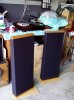
Pic is the speakers after I did the "sharpie" trick to the glue bleed through...
:banana: :banana: :banana: :banana:
 

Attachments

  • FRONT WITH SHARPIE.jpg
    FRONT WITH SHARPIE.jpg
    174.6 KB · Views: 250
Those look magnificent... like brand-new.

I've been thinking about doing a half-a$$ed restoration of my Timewindows, but it's probably better to do nothing or go for the gusto. Don't suppose you'd like to contract to do a pair of Timewindows, OMI? :-)
 
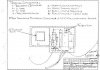
Called DCM today and they were kind enough to send me the schematics for the X-Over. Now all I have to do is order the correct caps. Is there an issue with replacement caps at a HIGH voltage???? Looks like the ones on the schematic are 50 V and the ones in the PE catalog are much higher???

omi
 

Attachments

  • TF350 Schmatics.jpg
    TF350 Schmatics.jpg
    125.2 KB · Views: 219
  • TF350 Schmatics02.jpg
    TF350 Schmatics02.jpg
    125 KB · Views: 240
TY...

Will go for the GUSTO:)

:banana: :banana: :banana: :banana: :banana: :banana:


Just ordered a set of caps from PE through the A.K. link so a bit of my $$$ will go back to A.K. :banana:

This will be my FIRST RECAP!!!!!! :D

When I am done I will have re-worked these TF350s from top to bottom.... :music:
 
Last edited:
O.K. ...

Being ELECTRONICALLY CHALLENGED I looked at the schematics above and the PE book and matched up some CAPS to the values shown on the above schematics.

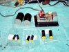
Received the CAPS today. All the CAPS were larger than the existing ones, BUT one was HUGE!!! The 47 mf CAP?????? What did I do wrong????

3 of the 4 CAPS were under the Dayton Metallized Poly section rated at 250v. They are not to bad in size.

BUT the 47 uf... I ordered 2 Solen metallized Poly CAPS and they are almost as big as the entire X-Over????

Comments???
 

Attachments

  • caps.jpg
    caps.jpg
    139.9 KB · Views: 208
I don't think you did anything wrong. I have only recapped one pair of speakers, and I used the Daytons. They were quite a bit bigger than the caps I took out. I think the nice ones are just a lot bigger!

Take care,

Ed
 
yeah, i saw it meself, the cap in the woofer circuit on the schematic is a 47 uf. you're prolly gonna wind up gluing them onto a separate board adjacent to the main one....
 
Hmmmm

I will look at BOTH X-Overs tonight reeeealy close and make sure the existing CAPs is a 47 and NOT a 4.7 or .47....

That Solen is rated at 400v as I could not find a 47 at a lower voltage... The one on the schmatic is rated at 50v. Is there another source I can go to for a lower rated (voltage) CAP?
 
Last edited:
Polypropylene, Polyester and Mylar caps are much larger than electrolytics. That's why it's so huge and that's why DCM used the electrolytic. Make a metal bracket for it and screw it to the inside of the enclosure, and connect it to the crossover with wires.
 
Warren,

Been thinking about how to do this? Cut the OLD CAP off and leave the connector ends sticking up from the PC board to solder the NEW connection wire to, then solder to the connectors on the CAP. Would it make sense to place the rest of the NEW CAPs on the same board and wire back to the PC board the same way. IE cut the old CAPs from the board leaving the stub-ups to solder the NEW connector wire to???
 
The best way is to go to Radioshack and buy some de-soldering braid, or a solder sucker (they have a really nice one that looks like a fat hypodermic for $7.00 or so) and remove the caps from the board using one of the above. Then solder the new caps to the board, staking them down with some RTV so they don't vibrate and break the leads.
 
Back
Top Bottom