• The move to the new server is done. There are some software and database maintenance updates in process. This has us passing the hat around to help out. We appreciate any donations. Seriously, even a dollar helps. The payment page may be found here - https://www.audiokarma.org/support.html

TPA 3116 vs the tripaths

I hate to ask the same question twice, but a while back (post #1415) it was stated that you could avoid the on/off speaker pop issue by placing a small capacitor across the switch contacts. I took this to mean that you would place the cap with one side connected to the power input side and the other capacitor lead attached to the switch contact leading downstream to the amp. Can someone tell me if this is in fact the correct interpretation and, secondly, if it would work? Seems like an easy answer to the problem, but I know virtually nothing about electronics. Can anyone with a better understanding comment?

I think this notion has two things confused, namely the spark and its associated sound that a mains switch can make when toggled, and the noise that an amplifier can make when turned on or off. Putting a capacitor over the switch will prevent the former but not the latter.
The spark issue will only happen if the switch is on the mains power by the way, so before your power supply. In that case you can add the capacitor to prevent any sparks, but it has nothing to do with speaker pops when turning on/off the amp.
 
Last edited:
I think this notion has two things confused, namely the spark and its associated sound that a mains switch can make when toggled, and the noise that an amplifier can make when turned on or off. Putting a capacitor over the switch will prevent the former but not the latter.
The spark issue will only happen if the switch is on the mains power by the way, so before your power supply. In that case you can add the capacitor to prevent any sparks, but it has nothing to do with speaker pops when turning on/off the amp.

Thanks, phalanger! You are another great example of the experienced helping us beginners in a clear and helpful way. I really appreciate Audiokarma and its members for that reason. Among others.
 
But I think it is mainly when you switch DC, not when you switch AC, the spark issue. And that spark when switching DC isn't always solved with a capacitor I read. I don't switch DC so couldn't tell from experience.
 
So no 200wpc monos?

I'm figuring out how to turn my 300B into an active pre. I want the best TPA monos to mate it with.
 
gang,

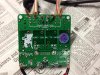
i need your help! i have the mini board from hiamplifier and am trying to wire it up. i have the schematic he posted: http://www.hiamplifier.com/TPA3116/TPA3116_BOARD_50X50MM_FINAL.JPG

i have the wires pushed through the holes right now as i want to make sure it works before i solder it up.

for power i have a nice laptop brick that measures out correctly on my multi-meter (just over 19V). i know which lead is positive and have that run into the VCC hole and the other to the ground.

all i get is a popping noise on the right channel. i am reluctant to start switching the wires around on the chance that the schematic is incorrect.

i recently fried my audiobah green board, which took forever to arrive, because i was using a bad power supply--so i am trying to be extra careful...

is the board defective? will it only work if i solder the wires and ensure a good connection? have i read the schematic wrong?:scratch2:

thanks!
 

Attachments

  • hiamp mini1.jpg
    hiamp mini1.jpg
    103.8 KB · Views: 94
  • hiamp mini2.jpg
    hiamp mini2.jpg
    74.6 KB · Views: 79
gang,

i need your help! i have the mini board from hiamplifier and am trying to wire it up. i have the schematic he posted: http://www.hiamplifier.com/TPA3116/TPA3116_BOARD_50X50MM_FINAL.JPG

i have the wires pushed through the holes right now as i want to make sure it works before i solder it up.

for power i have a nice laptop brick that measures out correctly on my multi-meter (just over 19V). i know which lead is positive and have that run into the VCC hole and the other to the ground.

all i get is a popping noise on the right channel. i am reluctant to start switching the wires around on the chance that the schematic is incorrect.

i recently fried my audiobah green board, which took forever to arrive, because i was using a bad power supply--so i am trying to be extra careful...

is the board defective? will it only work if i solder the wires and ensure a good connection? have i read the schematic wrong?:scratch2:

thanks!

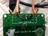
I would avoid applying power to the board with the wires just hanging loose in their holes like that - get the wires right and solder them up. You can always desolder them if really needed (but really, better to get it right the first time :)). Other than that, the signal ground doesn't seem to be connected. In case of any doubt after wiring it up, or worries about possibly faults on the board itself, use a multimeter to test the output before connecting your speakers and see if the readings make sense when increasing the volume from zero. I always do this as a precaution.
 
Last edited:
phalanger,

thanks for the reply. i'm an electronics noob and have now read a bunch of threads on signal ground but still don't know what i should be doing. is that the AGND on the schematic?

i did notice that there is a potential bad solder -- see solder blob to the left of the center top hole and the PBTL stencil. or is that normal?
 

Attachments

  • hiamp mini3.jpg
    hiamp mini3.jpg
    68.8 KB · Views: 76
The signal cables come with a lead and a ground. By the looks of it, you have used only one of them. Looks actually like you only connected the grounds and not the leads. the outer shell, when peeled, will typically have a plastic covered thin lead (red for right, white for left) and also copper strands that don't have their own husk, this is the ground.
The grounds for L+R can be tied together and connected to the common ground, if no seperate ground connectors are present, like here.

When the input connections are fixed, you can solder it down and continue.
I can't see from the pic if its a bad solder really, but I think the existing solderings on the board are probably the least of your worries here :)
 
Last edited:
I just got my SMSL SA-36a Pro (TPA3118) today. Very nice enclosure/build quality.

Need to do more comparisons with my Denon PMA-757 but it obviously does not have the same authority or amount of bass, which was as expected (although I was hoping to be surprised), compared to the 80wpc@8ohms amplifier. I'm sure some larger power supply caps and power supply would help. I might try building the 3116 to see if there's much improvement, but I was honestly hoping for a more authoritative sound. This still sounds miles better than the Tripaths I've heard though.
 
Sometimes, depending on source, signalground soldered directly on powersupply ground connection is more quiet, pbtl-n is another possibility.

The solderpad for pbtl you found connected seems an additional path to ground for the already grounded right channel negative input. I remember soldering it and desoldering it, not sure what is the status now on my own boards. Maybe if you hear a hum it could be from there or if right channel has louder turn off pop then left, that could be there then too, but it also could be softer, remember you connected your left speaker to the right channel output if you hear differences and try to locate source! Did you put pcb on some hard plastic to prevent shortcircuits to cool metal enclosure?
 
remotecontrolled 3116

I received the 3116 with display and IR remote. Bought it with 1 week left in May, so took little over 1 month. Bought at alsotao.com, they give you tracking ID and upload pictures of the package they sent to you. It came in a cardboard box with dents and brushes, board and parts look ok except for tiny little Elna ecaps that were bent a little and some legs seem to be touching, easy fix, but I guess you do have to check, no sound if legs are touching!

Connected pcb and blue display and green led all wellcome me, aux1 is source, volume says 15, music starts playing from cd I connected to 1 of 3 inputs on pcb, turn up volume, all works nice and music plays. But music sounds very different, bass is at +14dB, treble is at +14dB and loudness is on :) Ok range is -14dB to +14dB for bass and treble, buttons for it on remote :) Sounds better now, tonecontrols flat, will let it play a little :)

2rnbpc8.jpg
 
got my dynaco st120 conversion with the hiampmini completed (thanks to phalanger!). here are pics:http://albums.phanfare.com/isolated/U1QobTfv/1/6575721

now to let it run for a while!

Looks good in the Dynaco case! Do make sure the circuit board is isolated from the metal case though, unless you've made VERY sure that it is a non-conductive alloy. Just pointing the solder joints upwards is asking for trouble, assuming the metal does conduct electricity.
 
Back
Top Bottom