• Check out the Annual AK Secret Santa exchange Program, signup before November 23rd in the AK Charities & Christmas forum!

Transistor Substitutions

Yes. That is a long list!. How do you know that all these parts need to be changed?. what is the issue with your tuner, and have you isolated where the fault is?

I am sure some are just fine to leave alone. This is my first project unit (bought for cheap), so doing all for fun and practice. Plus should lower floor noise quite a bit.

No issue with tuner. I'm not replacing any on the tuner board(s), just the other ones.
 
unless you have FM alignment gear, I would very much suggest leaving all of the stuff in the tuner and MPX board alone.

as far as noise floor stuff goes, I think your biggest bang is going to be in the phono, preamp, and tone amp circuits. If there are carbon comp resistors, replacing those may actually give even bigger improvements than the resistors.
 
Here's my current list. Any feedback? Could use some help deciding between a few options and vetting these selections.

. . .

FM MPX:
2SC828Q (TR301, 302, 303) = KSC1845 or KSC945
2SC828R (TR304) = KSC1845 or KSC945
2SC1318S (TR305) = KSC2690

FM IF:
2SC710C (TR202, 205) = KSC1845
2SC710D (TR201, 203, 204) = KSC1845
2SC711 (TR206, 207) = KSC1845

unless you have FM alignment gear, I would very much suggest leaving all of the stuff in the tuner and MPX board alone.

As @gadget73 said, replacing transistors in RF-signal circuits is a bit more tricky than just audio-based ones. You need to watch careful to maintain the same Cob and same-or-better Ft... so the RF signal does not get cutoff due to unplanned capacitance and does not fail to get amplified by a too-low transition frequency. Totally do-able, but you have to be more careful and you cannot just throw common-substitution transistors in there.

Some starter info (certainly not complete or authoritative):
 
unless you have FM alignment gear, I would very much suggest leaving all of the stuff in the tuner and MPX board alone.

as far as noise floor stuff goes, I think your biggest bang is going to be in the phono, preamp, and tone amp circuits. If there are carbon comp resistors, replacing those may actually give even bigger improvements than the resistors.

I was wondering about this! In addition to the few boards you listed, I was planning on replacing transistors on the FM MPX and IF boards (no tuner or AM IF). Would that require FM alignment? I don't have an oscilloscope or signal generator handy, so may have to rethink approach if so...

Any tips on how to spot carbon comp resistors? Quick google image search shows resistors with 4 multicolored stripes...
 
ny tips on how to spot carbon comp resistors?
I can spot a carbon composite a mile away..Just by its physical shape..

articles-articles-carbon-composition-resistors-1319369885.jpg
 
As @gadget73 said, replacing transistors in RF-signal circuits is a bit more tricky than just audio-based ones. You need to watch careful to maintain the same Cob and same-or-better Ft... so the RF signal does not get cutoff due to unplanned capacitance and does not fail to get amplified by a too-low transition frequency. Totally do-able, but you have to be more careful and you cannot just throw common-substitution transistors in there.

Some starter info (certainly not complete or authoritative):

Incredibly helpful! Thanks so much for sharing; was unaware of this prior to now. Is this an accurate summary?

Cob
  • Early stages: can be ignored
  • Mid stage/"VAS" and power supply: equal or lower --> what boards are considered "mid stage"?
  • RF-signal (ie. FM MPX): as close to equal as possible (no large differential)
ft
  • RF signal (ie. FM MPX): equal or greater (within reason)
hFE
  • RF signal: similar range, tighter overlap the better
 
But some are molded wirewound in the same shape. :D The brown is usually a shade lighter, and you can see the mold seam.
Some color coded chokes look similar as well..Yamaha C-80/85 has eight of them in the phono equalizer section.
 
Ah, so don't swap in even some carbon film resistors? This is my practice unit, so I'm game to update unless there's more con than pro to doing so.
 
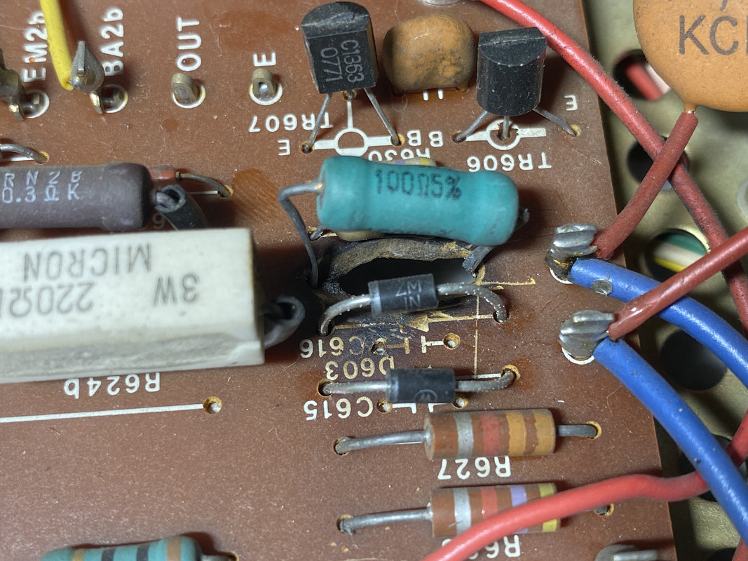
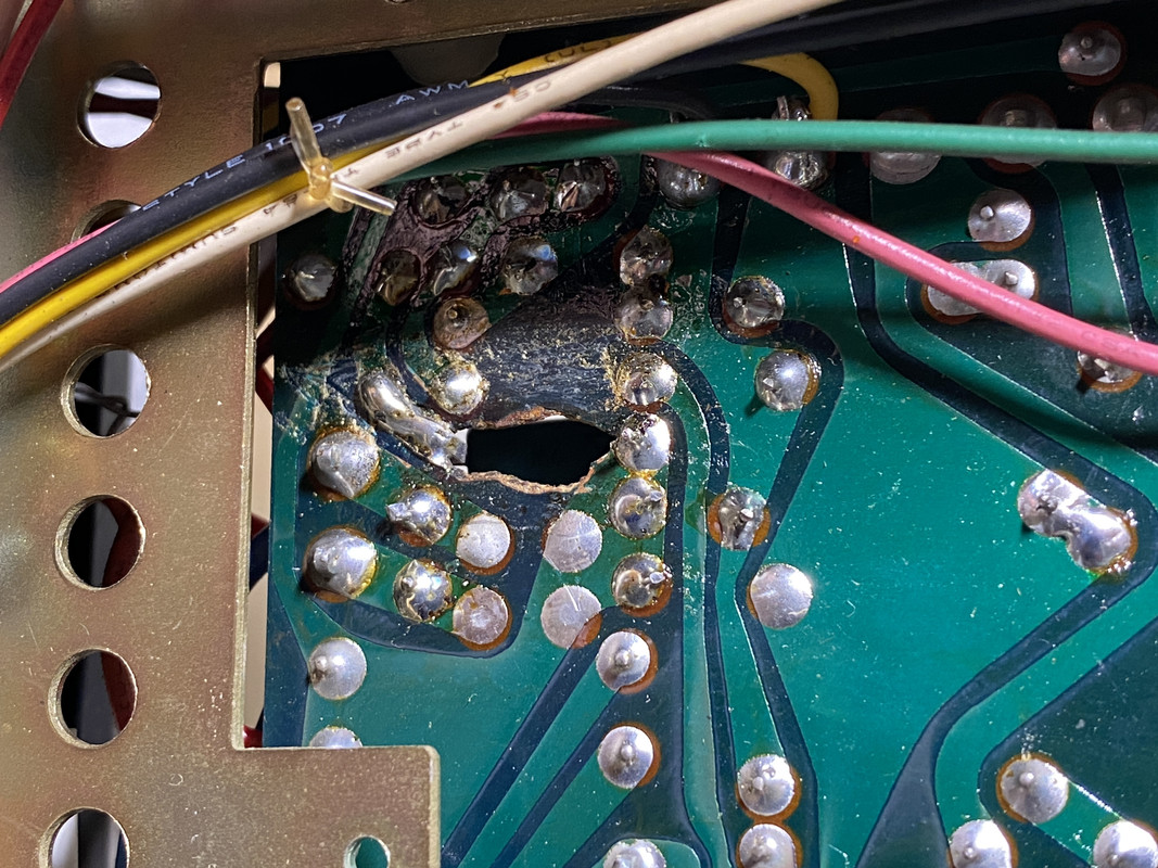
Check the solder joints on the 100Ohm (big blue one). It looks like the board is a little cooked there.

Good eye. R631 (2W, 100ohm) is a known toasty resistor for Sherwood's at least (another instance). It burned a hole in my PCB prior to my ownership and someone replaced with a new hefty one as best they could (potentially flame proof?). Bordering black diodes shown were also updated due to (I assume) being roasted!

Do these both look like correct replacements? I don't believe it's causing any issues nor has any contact problem. A little janky but if it works it works. Currently have a weak channel (hence why I'm refurbishing), but don't believe it's related.

IMG-6515.jpg

IMG-6514.jpg
 
I've done the same thing on a Kenwood KA-80 were the dropping resistor for the lamps, of all things, fried the board. Wonder if the original was on the board instead of elevated?

So long as the traces are good it should be fine.
 
I've done the same thing on a Kenwood KA-80 were the dropping resistor for the lamps, of all things, fried the board. Wonder if the original was on the board instead of elevated?

So long as the traces are good it should be fine.

It's very possible! Some resistors just don't play nice...

Since this repair was performed before my ownership, I'm more concerned that it was done with the right parts. Soldering seems to be fine but trying to determine if resistor and diodes (original V03C) are correct. Need some help doing so.

Btw, anyone know what kind of resistor this is? Easily dwarfs every other one on my board. Closest visual match I can make online is a metal oxide resistor which have some bulk.
 
Last edited:
Good eye. R631 (2W, 100ohm) is a known toasty resistor for Sherwood's at least (another instance). It burned a hole in my PCB prior to my ownership and someone replaced with a new hefty one as best they could (potentially flame proof?).

Good grief! Yes, that is really bad choice (by someone) of resistor and spacing around / above.

Modern resistors can be quite a bit smaller while dissipating same or more heat. Especially when you solder them in with plenty of room between board and resistor and other components.

I quite like Vishay's CPF series, available in 1W to 5W, for instances like this. I use a lead former to make crimps in the leads which then hold it up off the board by themselves. These orange resistors are modern Vishay CPFs stood-off by forming or crimping the leads:


IMG_0775 closeup.jpg
 
Good grief! Yes, that is really bad choice (by someone) of resistor and spacing around / above.

Modern resistors can be quite a bit smaller while dissipating same or more heat. Especially when you solder them in with plenty of room between board and resistor and other components.

I quite like Vishay's CPF series, available in 1W to 5W, for instances like this. I use a lead former to make crimps in the leads which then hold it up off the board by themselves. These orange resistors are modern Vishay CPFs stood-off by forming or crimping the leads:

View attachment 2697930

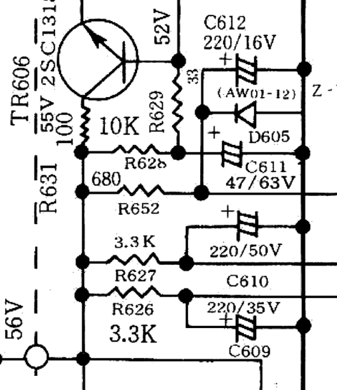
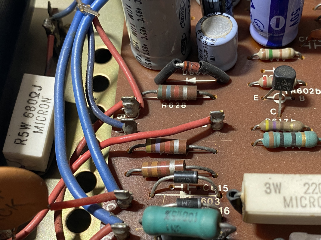
Thanks for the recommendation Doug! I like what I see. It hasn't sat right with me since I first opened up the unit. Am I good with 1W or should I bump up to 2W? Wondering if I should take this opportunity to also replace the three carbon comp resistors in the same area. I've had a few folks say leave them and a few other say rip them out. Always a mixed bag on here. Schematic above but "real" values below?

The ones in the picture aren't 100% like the values you are quoting, I make that 3.3KΩ, 1.8KΩ & 5.6KΩ. :idea:
 
The people who mentioned to rip them I believe were talking about in your signal path, not the power supply. In the power supply as long as temperature is good and voltages are correct and filter caps are fine (if they are rated for higher voltage than supply, then they often are fine) then your power supply is not worth focusing on. Signal path is where you want to focus. Listen to it between changes, see what you think. Your phone can be a signal generator, Function Generator app works great. You can get hand held oscilloscopes for like $50 - not the most reliable though. (JYETech will get you by, but have had problems with them) one that is known good working used can be found on ebay or even at surplus stores fairly cheap. Universities often have auctions with old tech gear too, local one to me has a couple going for $10 right now, just have to find one in good condition.
 
Good eye. R631 (2W, 100ohm) is a known toasty resistor for Sherwood's at least (another instance). It burned a hole in my PCB prior to my ownership and someone replaced with a new hefty one as best they could (potentially flame proof?). Bordering black diodes shown were also updated due to (I assume) being roasted!

Do these both look like correct replacements? I don't believe it's causing any issues nor has any contact problem. A little janky but if it works it works. Currently have a weak channel (hence why I'm refurbishing), but don't believe it's related.

IMG-6515.jpg

IMG-6514.jpg
that's nasty. Those power resistor do not just go open. They will cause that type of damage when something else goes bad in the circuit. Usually a transistor.

this one from a Yamaha C-1 PSU because some nasty 2SA561s turned into resistors themselves:
index.php


index.php

index.php
 
Back
Top Bottom