
• Check out the Annual AK Secret Santa exchange Program, signup before November 23rd in the AK Charities & Christmas forum!

Troubleshooting CD Players

Sony CDP-311

I am trying to oil the disk table motor bearing, I'm using a hypodermic-like needle to apply the oil. Below the metal plate is the motor which is flush against the plate so the needle can't get in there. Above the plate, the black plastic on which the table sits is too close to the plate for the needle to fit there either and I don't think I can find a smaller circumference needle. I don't have an angled driver to get at the motor screws to possibly drop the motor slightly so that I could get in that way but with the black plastic part holding it above I don't think I'd get enough clearance anyway. The only option I can see is to remove the table and plastic part. The service manual doesn't say how to do this removal. How is this done, or is there another option for accessing the bearing. I realize that removing the table could ruin the table height after replacement but again I don't see any other option.

View attachment 2948805
Don't remove the disc table, the height is critical. Usually there is enough slop in the motor shaft so you can lift it slightly to get the needle under the disc table neck, but if you can't, just apply the oil where the disc table neck meets the plate and the oil will wick in where it needs to go.
 
Ok, I'll have to look at the schematic. Something is pulling it down, but it's an active semiconductor not a shorted component.
For reference so I don't have to go back and look what player this is again, it's a Sony CDP-X555ES.
I believe you said:
1. You don't own a scope. That's gonna complicate things.
2. It worked after you replaced the caps, then stopped when you put it back together.
3. Measure the voltage on the + side of C294 and the + side of C923. Also verify that both caps are 2.2uF. If you had a scope I would have you check for ripple at these points. That could be why the voltage on IC903 pin 3 is 3V when it should be 5V. If there is ripple on the reset line it won't start.
4. Remove D906 temporarily and see if it starts. Check the voltages on IC903 pin 3 and pin 6.
 
For reference so I don't have to go back and look what player this is again, it's a Sony CDP-X555ES.
I believe you said:
1. You don't own a scope. That's gonna complicate things.
2. It worked after you replaced the caps, then stopped when you put it back together.
3. Measure the voltage on the + side of C294 and the + side of C923. Also verify that both caps are 2.2uF. If you had a scope I would have you check for ripple at these points. That could be why the voltage on IC903 pin 3 is 3V when it should be 5V. If there is ripple on the reset line it won't start.
4. Remove D906 temporarily and see if it starts. Check the voltages on IC903 pin 3 and pin 6.
Readings as follows:

C294 = 3.86v
C293 = 10.32v

Removed Diode D906, still didn’t start, readings:

Pin 3 = 3.64v
Pin 6 = 2.094v
 
Readings as follows:

C294 = 3.86v
C293 = 10.32v

Removed Diode D906, still didn’t start, readings:

Pin 3 = 3.64v
Pin 6 = 2.094v
It appears the caps are installed with the correct polarity. What brand are they and where did you buy them?
 
They are Nichicon part number UKL1H2R2KDDANA
I bought them from Mouser
Ok, not the parts, then. You need a scope at this point.
 
Ok, not the parts, then. You need a scope at this point.
Thanks for all the help @dr*audio I was saving to buy a nice oscilloscope for a while. I think I will buy one and I will reply here when I have it to continue the troubleshooting with your help.
 
Thanks for all the help @dr*audio I was saving to buy a nice oscilloscope for a while. I think I will buy one and I will reply here when I have it to continue the troubleshooting with your help.
The scope is to look at the reset line and see if it is a flat DC voltage or if it has ripple on it. When you post again, include the make and model of the player and that we are looking at the reset line at IC903.
 
Do you mean SPDIF OUTPUT? I can't see a CD player having an input. What would be the point?
Do you have an oscilloscope? You would need to probe the circuit and look at the signals.
I was using my computer with a USB to SPIDIF converter and then into the SPIDIF input on the player utilizing the inboard DAC. The input has gone silent. There is no schematic as far as I can see.
 

Attachments

  • IMG_2356.jpg
    IMG_2356.jpg
    137.5 KB · Views: 1
Some allow the DAC to be used. I think I was looking at this company's products the other day, as someone was lauding them.

Though it looks like some confusion here: the i3.3 is an integrated amp. The mating CD3.3 is the CDP:

You are correct cpt_paranoia, it is a CD3.3. It is a very nice machine with very solid build and looks to be very well engineered. Nice DAC and I will send it in for repair.
 
The scope is to look at the reset line and see if it is a flat DC voltage or if it has ripple on it. When you post again, include the make and model of the player and that we are looking at the reset line at IC903.
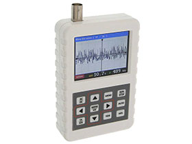
Hello @dr*audio I finally got a scope. This is for Sony CDP-X555ES you asked me to look at the reset line for ripple.

I used DC coupling with an offset of -5v and at pin 6 of IC 903 looks I have 100mv.

IMG_1925.jpeg
 
100mV of ripple shouldn't cause any problem. Now look at pin 3 of IC903. Please set the scope to 2V per division and set the trace to the middle line (0V offset) and DC coupled.
 
Last edited:
That looks fine. Ok, now we know the supply is ok, the reset signal is ok before the buffer (IC903) but something is loading the signal down on the output of IC903.
We need to narrow down what is loading down the reset line. Look at the layout below. Remove the 2 wire jumpers and replace them both with 1K resistors. Then, measure the output of IC903 pin 6, then the output side of each 1K resistor.
1692466477453.jpeg
 
That looks fine. Ok, now we know the supply is ok, the reset signal is ok before the buffer (IC903) but something is loading the signal down on the output of IC903.
We need to narrow down what is loading down the reset line. Look at the layout below. Remove the 2 wire jumpers and replace them both with 1K resistors. Then, measure the output of IC903 pin 6, then the output side of each 1K resistor.
View attachment 2962875
After replacing jumpers with 1K resistors:


Pin6 IC903= 4.89v
Resistance next to IC903 both sides = 4.89v
Resistance next to IC201 side facing IC903=4.89v
Side facing near connector = 1.74v
 
After replacing jumpers with 1K resistors:


Pin6 IC903= 4.89v
Resistance next to IC903 both sides = 4.89v
Resistance next to IC201 side facing IC903=4.89v
Side facing near connector = 1.74v
So now we know that the part that is loading down the reset line is in the lefthand part of the circuit.
1. Reinstall both jumpers.
2. Install a 1K resistor in place of the jumper near R314, and in place of the jumper below D907.
3. measure the voltage on both sides of the above resistors (just denote them by right and left side) as well as R230 and R360.
1692484747265.png
 
Back
Top Bottom