Hi Guys,
I am not sure this belongs to the Tube Audio forum but I didn't find a more suitable category.
I worked of this tester, a Sencore MU-150, that I found very nice so I am sharing this with you.
The good points:
- This tester is one of the last tube tester been produced, therefore is more modern than the classic oldies.
- It has a very sensitive as it uses a 12AU7 tube as voltage differential. The meter could pick up variation that my fluke couldn't.
- It does the classic tests for static emission, shorts, grid leakage and tube life.
- And does a superb job as trans-conductance test, by generating a 5 Khz signal to the tube and measure it that way. It has 3 transistors for that function.
- The voltage reference is also made with a tube too, an OB2 voltage regulator.
- It is a very robust and heavy piece of equipment. It has 2 transformers, one for the heaters and one for the tester itself. The case is a made of solid metal protecting the tester very well. The layout is clean and well design.
The weak points:
- The main problem is the PCB. Very brittle and prone to cracks. It attached directly to back the meter.
- The calibration is unnecessary complicated.
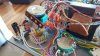
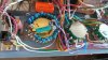
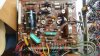
Here are some pictures.

Inside:

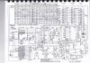
Here is the schematic:
Most of the components on the board were out of specs and had to be changed.
All external caps were bad.
But all the rest was in excellent condition.
So I first tried to change all components on the board and give it a try.
Here it is:
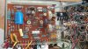
The tester was working. I used a SS voltage regulator too.
I was happy, but the board was still fragile, and the calibration wasn't easy as some resistor needed adjustment and without a trimmer, it the painful de-soldering/re-soldering process, try, retry.
I liked this tester so I decided to make a new board, and improve a few things.
- First I wanted all the caps to be mounted on the board and not externally mounted to the chassis.
- Increase within reason the PS filtration.
- I wanted to only use 1 tube, and replace the OB2 with a solid state solution.
- I wanted to shield the 12AU7 and keep it tied to the socket.
- Add trimmers were I needed to make the calibration easy.
- I added a current sensing resistor in the meter path so I could connect a VDM to it.
After 2 iterations, one without layout change (V1.0) and all these changes (V1.1), I got a perfectly working solution.
Here it is:
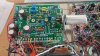
Only one tube mounted on a plate, shielded. All caps in the board, more trimmer, neon bulb on top, etc..
Here is it finished.

The calibration was easier.
1) The static emission needs a plug to be build with 2 resistors and a diode, as per the manual. Then you insert it and adjust the meter mid range with 1 trimmer. That calibrates the tube voltage differential for all measurement.
2) The GM emission calibration is a 2 step process. You need a 1600 ohm resistor to the arm of the signal pot, to the 0.47uf cap of the voltage amplifier (marked CAL in to board), as the user manual's instruction.
- Max signal first, you adjust the meter at 100% with 2 trimmers. Then forget about the scope things in the manual. Get a DVM and measure the voltage at the arm of the signal pot
- Min signal, remove the 1.6 resistor and adjust the voltage to 1/10 of what you measured before. That part is tricky.
And that's it. In fact they wanted the max signal to be 100% of the meter, and the min a tenth of it to have a linear range.
I added a fuse for safety, changed the neon bulbs (nice one from Radioshack), and all load resistors mounted on the rotary switch. Nothing difficult.
I am sure I am forgetting things but that's mostly it.
I like the ease of using of that tester. The little book has most of the tubes in it, you start by the shorts, then emission, then grid leakage, then gm emission then life test. Simple.
I attached my gerber file so anyone can have a PCB made for it.
And here is the rendered picture.
Thanks for reading.

I am not sure this belongs to the Tube Audio forum but I didn't find a more suitable category.
I worked of this tester, a Sencore MU-150, that I found very nice so I am sharing this with you.
The good points:
- This tester is one of the last tube tester been produced, therefore is more modern than the classic oldies.
- It has a very sensitive as it uses a 12AU7 tube as voltage differential. The meter could pick up variation that my fluke couldn't.
- It does the classic tests for static emission, shorts, grid leakage and tube life.
- And does a superb job as trans-conductance test, by generating a 5 Khz signal to the tube and measure it that way. It has 3 transistors for that function.
- The voltage reference is also made with a tube too, an OB2 voltage regulator.
- It is a very robust and heavy piece of equipment. It has 2 transformers, one for the heaters and one for the tester itself. The case is a made of solid metal protecting the tester very well. The layout is clean and well design.
The weak points:
- The main problem is the PCB. Very brittle and prone to cracks. It attached directly to back the meter.
- The calibration is unnecessary complicated.
Here are some pictures.
Inside:
Here is the schematic:
Most of the components on the board were out of specs and had to be changed.
All external caps were bad.
But all the rest was in excellent condition.
So I first tried to change all components on the board and give it a try.
Here it is:
The tester was working. I used a SS voltage regulator too.
I was happy, but the board was still fragile, and the calibration wasn't easy as some resistor needed adjustment and without a trimmer, it the painful de-soldering/re-soldering process, try, retry.
I liked this tester so I decided to make a new board, and improve a few things.
- First I wanted all the caps to be mounted on the board and not externally mounted to the chassis.
- Increase within reason the PS filtration.
- I wanted to only use 1 tube, and replace the OB2 with a solid state solution.
- I wanted to shield the 12AU7 and keep it tied to the socket.
- Add trimmers were I needed to make the calibration easy.
- I added a current sensing resistor in the meter path so I could connect a VDM to it.
After 2 iterations, one without layout change (V1.0) and all these changes (V1.1), I got a perfectly working solution.
Here it is:
Only one tube mounted on a plate, shielded. All caps in the board, more trimmer, neon bulb on top, etc..
Here is it finished.
The calibration was easier.
1) The static emission needs a plug to be build with 2 resistors and a diode, as per the manual. Then you insert it and adjust the meter mid range with 1 trimmer. That calibrates the tube voltage differential for all measurement.
2) The GM emission calibration is a 2 step process. You need a 1600 ohm resistor to the arm of the signal pot, to the 0.47uf cap of the voltage amplifier (marked CAL in to board), as the user manual's instruction.
- Max signal first, you adjust the meter at 100% with 2 trimmers. Then forget about the scope things in the manual. Get a DVM and measure the voltage at the arm of the signal pot
- Min signal, remove the 1.6 resistor and adjust the voltage to 1/10 of what you measured before. That part is tricky.
And that's it. In fact they wanted the max signal to be 100% of the meter, and the min a tenth of it to have a linear range.
I added a fuse for safety, changed the neon bulbs (nice one from Radioshack), and all load resistors mounted on the rotary switch. Nothing difficult.
I am sure I am forgetting things but that's mostly it.
I like the ease of using of that tester. The little book has most of the tubes in it, you start by the shorts, then emission, then grid leakage, then gm emission then life test. Simple.
I attached my gerber file so anyone can have a PCB made for it.
And here is the rendered picture.
Thanks for reading.
Attachments
Last edited:

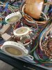
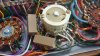
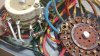
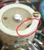
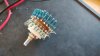
 I do need some advice as I messed up my 'Load Switch' when cleaning the pots and switches on my MU150 tester recently bought. The load switch consists of 4 separate switches as shown in the photo. I tried to take them apart and clean them individually. The problem is that I do not remember where the switch knob was positioned when I took out the 3 switches starting from the upper section. The last switch was not removed so that one is fine. the other 3 are in alignment but I am not sure how to align them with the last 4th switch. I turned the knob clockwise/counter clockwise many times without thinking