• The move to the new server is done. There are some software and database maintenance updates in process. This has us passing the hat around to help out. We appreciate any donations. Seriously, even a dollar helps. The payment page may be found here - https://www.audiokarma.org/support.html

Tube tester: Sencore MU-150

This is very cool. I have a Sencore Mu140 and 150, only slight circuit changes between the two. I've rebuilt both of them but both aren't working in different ways after their rebuilds so they have been parked for over a year.

How might I go about getting some boards built using your gerber files and do you have any idea of the cost?
 
3) Yes. the CC resistors most likely have all drifted. And on mine the transistors were measuring DC ok, but were not working. So SS do age too... :)

Silicon doesn't fail from age.

The problem with older transistors is purely manufacturing: the interior of the case was tin-plated, and tin, over time, grows whiskers. This is why many of the older germanium transistors became noisy or outright failed.
 
This is very cool. I have a Sencore Mu140 and 150, only slight circuit changes between the two. I've rebuilt both of them but both aren't working in different ways after their rebuilds so they have been parked for over a year.

How might I go about getting some boards built using your gerber files and do you have any idea of the cost?

I go there: https://jlcpcb.com/
Get a quote and upload the zip file and you'll see.
 
Silicon doesn't fail from age.

The problem with older transistors is purely manufacturing: the interior of the case was tin-plated, and tin, over time, grows whiskers. This is why many of the older germanium transistors became noisy or outright failed.

i should have opened open one and see. Oh well.
 
Hi, I recently bought Sencore MU-150 that needed restoration. I replaced all electrolytic capacitors so far, and replaced 5 resistors in Emission test circuit. I tried to calibrate to no available (couldn't reach the center of the dial with R34 at zero, all the way to the right), so started troubleshooting.

My voltages are way too low around 12AU7 vacuum tube. I do get -216V and +210V to the circuit from the power supply, but my anode voltage is 80-85V instead of 105V (I am running 117VAC source through variac), my cathode voltages are 2.8V instead of 4.2V on both cathodes.

I am also reading a very weird voltage on pin 1 of voltage regulator: 35V instead of 117V. Swapping regulator with another NOS vacuum tube didn't help. Swapping brand new 12AU7 brings cathode voltages to 3.1V, but doesn't help much.


One question - what is the purpose of I2 neon light bulb that is connected near Meter Zero? It seems to go nowhere - mine was burned off and was flying around inside tester suitcase. I have a spare small Neon bulb (not NE-2, but very similar), so I can solder it in. Would missing I2 cause my problems? Why is that light bulb even there, as it does not illuminate anything, unlike I1 and I3?

Thank you.

 
Did you check the resistors? On my original board, they were totally out of tolerance.
This may explain the voltages gap.

For the Neon lamp I don't think so. I guess it is there to indicate that the voltage regulator is working. I never paid much attention.
There is a resistor under the board too if I remember correctly.

The original board is prone to micro cracks very hard to see so it is difficult to make sure the circuit is operational.

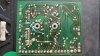
Here is a pic of the copper side of the original board. I hope it helps

20181214_104054.jpg
 
Last edited:
Thank you. I'll hunt through the traces. I installed new neon bulb, just to realize that it's useless and pinched one is those under board wires, and almost fried transformer... Lucky so far.
 
Could use some help here. I have the PCB's from jlcpcb and ordered the BOM. Was ordering so many parts for different projects didn't realize some things didn't match up.

1) I see six different type of diodes/rectifiers in your BOM. What are the values of:
Z1 to Z3 - I assume 1n5365 goes here and that 1n5938 is a lower wattage equivalent
CR5 - ?
CR6 - ?
CR7 - ?
CR8 - ?
CR9 - 1n34a is NLA germanium diode. Is 1n5817 supposed to go here?
CR10 - 1n34a is NLA germanium diode. Is 1n5817 supposed to go here?
CR12 - ?
CR13 - ?

2) What part should I order from Mouser for NE2? And whatever silicon that is on the left of it on the PCB?

3) Capacitors:
C1 & C2A - Your BOM lists 100uf and not 82uf. I assume these are just the power supply caps and increasing to 100uf is just fine
C16 - PCB has axial 10uf unknown voltage rating. Your BOM has a 22uf 250v axial capacitor. Which is correct for this position?

Thanks
 
1) I see six different type of diodes/rectifiers in your BOM. What are the values of:
Z1 to Z3 - I assume 1n5365 goes here and that 1n5938 is a lower wattage equivalent: BH: Yes, 3 x Zener 36V 2W. I put 5 W.
CR5 - ? BH: 1N4007
CR6 - ? BH: 1N4007
CR7 - ? BH: 1N4007
CR8 - ? BH: 1N4007
CR9 - 1n34a is NLA germanium diode. Is 1n5817 supposed to go here? BH: 1N34A replace with a BAT46.
CR10 - 1n34a is NLA germanium diode. Is 1n5817 supposed to go here? BH: 1N34A replace with a BAT46.
CR12 - ? BH: Replaced the diode at CR12 with a 1N4007 and 1N5817
CR13 - ? BH: 1N4007

2) What part should I order from Mouser for NE2? And whatever silicon that is on the left of it on the PCB? Yes I got mine from Radioshack. Any NE-2 will do, 65-120VAC. It is a bridge rectifier like a MDA106G.

3) Capacitors:
C1 & C2A - Your BOM lists 100uf and not 82uf. I assume these are just the power supply caps and increasing to 100uf is just fine BH: Exactly.
C16 - PCB has axial 10uf unknown voltage rating. Your BOM has a 22uf 250v axial capacitor. Which is correct for this position? BH: Correct.
 
I have had some time to work on the MU 150 recently (not giving up until it is perfect!),
and here is what I have done.

1. I have checked for pcb cracks, the pbc seems ok, maybe later will buy a new pcb..
2. Replaced all the resistors and caps on the pcb and the load switch.
3. Removed the ne2 bulb on the copper side of pcb including the 2 resistors that are connected/near to it. (is this a mistake?)
4. Changed TR1 to BC549, TR2 and TR3 to 2N2222
5. CR12 = 1n4007 + shotky in serial (forward voltage around 0.7v), R23 =270 ohm, r25 = 1k ohm, r35= 510ohm (as in the later MU150 manual, and what is recommended online)
6. Opened up cleaned the signal pot, but the 5K section still a bit jumpy.. I will buy a new 5k/50k pot soon.

Now when I test any 12AX7 tube for mutual conductance, my gm readings are too high.. above 120% in the scale and the meter on the far right end..
There must be something wrong since some of the tubes are really old and weak.. Can't measure this high..

I was able to calibrate the emissions at 60%, and gm high signal at 100% without any problems..

Should I use a single 1n4007 for CR12 instead? or change any resistor values on the gm signal path?


Could it be the signal pot or replacement transistors that do not match the original spec?

Can I change the 1n34a diodes to 1n60?

Almost getting there pls help
 
Last edited:
Hi,

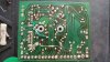
First I would add back the 2 resistors and the NE2 bulb. Here is a pic.
I would also check with a scope if your square signal is correct looking before going further.
 

Attachments

  • 20181214_104054.jpg
    20181214_104054.jpg
    133.6 KB · Views: 67
Looks like the NE2 might be acting as a voltage regulator? Seems like it would need to be there either way.

are the 1N34a actually bad? Pretty sure you can still get that exact diode new.
 
Thankyou Brice and gadget73!

I have soldered back the neon bulb and the two resistors and wow, some changes occurred.. but in a bad way..

When trying to calibrate for emissions, the meter is already reading 35% even without the calibration module connected.

When the calibration module is connected, the readings are too high and I cannot get the meter down to 60%.. 70% is my best with the
adjustment pot fully turned down..(this was done with ease, set at 60% when the neon bulb and two resistors were removed.
I actually removed the pcb copper side bulb + 2 resistors when I bought the MU150 two years ago thinking they were broken backlights. haha

Also, the gm high signal calibration is now somewhat off, 80% on the meter is the best I can go up to.

I am assuming my NE2 bulb is faulty since it adds all these weird problems, is it supposed to lit up? mine does not..
Or should they only lit up during actual gm tests? How can I test if it is good or not?

If I need to buy new NE2 bulbs which type should I choose? There seems to be variations.

What is the original value of the two resistors? One seems to be R47 - 3.3M ohm, I could not locate the other one in the schematic..

My 5khz square signal seems to be present checked on a 25 dollar toy oscilloscope.

The two 1n34a diodes are ok but measures differently (Vf 0.34v, 0.37v)

I will buy/replace them too, with new 1n34a diodes.

Truly appreciate the help,
Thanks again guys!
 

Attachments

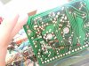
  • DSC_0089.JPG
    DSC_0089.JPG
    113.8 KB · Views: 32
The neon bulb is, of course, used as a voltage regulator. The exact strike voltage depends upon the bulb type, often with specific characteristics created for use as regulators. The ordinary bulbs generally are 90 V, but regulators exist for voltages roughly between 50 V to 150 V. So best look up the bulb type.

A modern zener diode is vastly superior, of course. The early zeners (both germanium and silicon) had poor leakage characteristics and temperature stability, issues, both of which no longer affect modern components.

A germanium diode's Vf varies with current, and the standard 0.3 V can drop to as little as 0.1 V.

Many of the diodes sold as germanium are silicon. Beware the eBay purchases. Russian will be perfect.
 
R46 is a 2.7M.
I used a 90V NE2 and yes I seem to remember it does glow.

I can't really see in your picture but the 3.3M is only connected to the bulb and no trace touches the point NE2/R47 3.3M.
I know it's confusing but in your picture it seems like the 3.3M is connected to the PCB?
 
DSC_0098~2.JPG Hello again

I am uploading a photo that is more clear. Sorry for the confusion the black insulation tube
on the resistor may have gotten in the way.

I think the connections are properly made as in Brice's pic. (corrections, I misunderstood your sentence.. The bulb and r47 connection should not touch any pcb trace. I connected them to the trace.. I will disconnect now and see if it works)
Meanwhile I will visit a local electronic s store
and find a new signal pot. Will buy two and swap the wafers. 5k + 50k.

Thankyou so much
Really appreciate all the help provided!
 
Last edited:
Back
Top Bottom