• The move to the new server is done. There are some software and database maintenance updates in process. This has us passing the hat around to help out. We appreciate any donations. Seriously, even a dollar helps. The payment page may be found here - https://www.audiokarma.org/support.html

Tube tester: Sencore MU-150

Hey all,

I'm getting ready to order the parts to proceed on this. I have the new board in front of me. I have a couple quick questions.....

  1. Is it safe to assume all the resistors on the board are 1/2w unless otherwise specified?

  2. On the replacement pot with the stepped 24k rotary switch, it looks like the 2.5k resistors are 1/2w, and the 250Ω resistors are 1w? Is that correct?

  3. What tolerance should all the resistors be?

  4. Are all capacitors now on the board? Are there any caps that should be ordered at the same time that are not included in the BOM?

  5. Does the little neon bulb get re-used?
 
Hi Dogwan.

1) Yes.
2) Does not have to be 1 W. Can be 1/2W. There is no need.
3) 1% - 10% as usual.
4) Yes. No external mounted cap. All caps are now on the board :)
5) Yes you need a neon bulb also on the new board.

Good luck with your build.
 
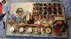
I started working on my MU-140. Got the board all populated and most of the off-board resistors and caps changed.

I ended up with a couple extra parts that I can't locate:
  • C19 (0.047uf/1kv MLCC), I believe this is off the board but I cannot locate it either physically or on the schematic for either the MU-150 or 140.

  • C18 (0.002uf/250v MLCC), there was qty. 2 on the BOM, I assume I only need one but there is an extra. I cannot figure where this is supposed to go.

  • R16,17 (150Ω/1/2w), these were on @The Ruined 's resistor list. There is already an R17 that is 150k and is clearly labelled on the board.
Any hints where the above go?

I also ran across the following issues:
  1. R23 is labelled for a 270r adjustment trimmer, but I had a leftover 500r trimmer. I assume that that would just give me a bit extra adjustment range?
    (I pulled R23 from the old board and color code says it should be 390r, but it measured 407r)
    I installed the 500Ω and adjusted it to 270Ω.

  2. N-2 bulb on BOM was 65vac/0.7ma instead of the 90v on that @Brice mentioned earlier in the thread.

  3. The "Shorts" bulb on the original board was soldered to pads 6 and 7 with short leads and sat in the holder underneath the corner of the board. I plan on soldering on flying leads to the bulb and solder to the top side of the new board.

  4. The tube socket bracket didn't fit into the new board. I had to use a Dremel to grind the pins down to fit into the holes. And the bracket had to be spread a little. Don't know if they used a different bracket on the MU-150, but they look the same.

  5. I am a little concerned that C1, 2a, and 2b may be a little tall to fit back into the case when it's all assembled. It's going to be really close.

  6. I skipped replacing C5,15 on the FUNCTION switch. It was going to be too hard to get to the solder connections without risking damage and they appear to be non-critical decoupling caps to ground.

  7. I skipped replacing R42 and C14 on the LOAD switch. It was going to be too hard to get to the solder connections without risking damage and they appear to be non-critical decoupling network to ground.

  8. There's a weird three legged resistor on the LOAD switch that is labelled 140 / 160. I believe this is a split resistor that totals 300Ω. I didn't see this on the BOM or on the resistor list. It measures 170Ω and 144Ω instead of 140Ω and 160Ω respectively. It looks like it might be a 10w (?) resistor. Maybe this is R16?
 
My next step is to bolt the board back in and start hooking the wiring back up.

I am also going to start reading up how to calibrate this sucka!

Any hints on how to combine the procedures in the manual and the newly engineered board?
 
Ok, I got it all re-assembled only to discover that, of course, my F Signal pots are all buggered. Gonna have to order those parts in before I can really calibrate this tester.

However, I was able to build my Emission tester jig and that function calibrated up like a champ. The first tube I tested was the 12au7 that had been in the Sencore ever since I got the tester (I just put in a known good 12au7 upon bolting the board back in) and wouldn't you know it that 12au7 was really bad.

Anyway, I went through a bunch of tubes that I had tested for emissions before and getting much better readings. The tubes are testing around 10 points higher consistently than they did before. Can't wait for my Gm tests to be working.

I did find another thread on another forum where @Brice gave more details of this board......
https://www.antiqueradios.com/forums/viewtopic.php?f=8&t=167756&start=80

Reading through that thread I think I answered a couple of my own questions.
  • It looks like C18 (0.002 ceramic cap) was a later revision circa '71 on the shorts test, so my unit wouldn't have had this part.
  • Based on the numbering I think that C19 (0.047 ceramic) might also be a later revision, so I'm not going to worry about it.

  • R23...I think that this was spec'd as a trimmer because there seems to be some discrepancy between the different versions of schematics and the actual part. R23 in my schematic is 270Ω, but I found a 390Ω resistor that had drifted high. Others in that thread also mentioned having 390Ω parts. I went ahead and set the pot for 390 as it's not mentioned anywhere as being part of a calibration process.

  • R35...I believe this is a trimmer so that you can use the 10Ω sensor at R35a and adjust to get the total 470Ω. I set it for that by measuring across R35 and R35a in series and adjusting to 470Ω total.
    I'm still a little bit confused by this and the markings on the board for using a DVM to achieve 0 - 0,01vdc.
    But, if I understand correctly this is to make adjusting the lower end of the Gm calibration without a scope? Reading what Brice said on page 4 about the sensing resistor, it looks like I follow the manual for setting the high Gm calibration and measure across the sensing resistor should yield about 10mv (not sure if supposed to adjust R35 at this point) after setting R24 to get 100 on meter scale. And then after removing the 1600Ω resistor from wiper to "CAL" on board and setting F Signal pot to "1", then should be able to read across the sensing resistor to 1/100th of current (or 0.01mvdc) by adjusting R21.

    Whew, luckily I have some time to wrap my head around this. I may have to ping Brice and see if I can get him on the phone.

    Oh yeah, I already have my 1.6k resistor for the Gm calibration. Had a nice 3 watter that measured 1597Ω. I soldered leads to it and now it measures 1602Ω, which should be good enough for this procedure.
 
Reading through that thread I think I answered a couple of my own questions.

Your rebuild progress is excellent material for anyone contemplating or performing this project on their own, and very useful; I both thank you for posting it, and hope that you will continue to post the analysis. At least one of us finds it valuable.

I have not yet rebuilt my Sencore tester, but this is exactly the sort of material than can rapidly and effortless resolve issues as they arise.

Again, nice work!
 
24 position stepped attenuator ordered.

However, I am having a really hard time locating the 250r and 2.5k resistors. They seem to be an odd value. Of course I could get them from Mouser but it will be pretty expensive. I've scoured Ebay and come up empty handed.

Anyone have a good source for these for not too much cost?

Also, does anyone know if we can get away with 1/4w resistors on the build out of the pot?
 
Hi Dog,
I am just catching up.
Yes the caps I've used are not as tall as the one you have, this may be a problem. I used 100uF 250V 20mm tall 647-UCY2E101MHD @ mouser.

I checked my records and I did use 2.5K 1/4 W resistor too. There is no high current going on the double pot so I would say yes too for the 250R.
I checked and I don't have these resistor values on hand, else I would have send you what you need. Bummer.
 
Thanks Brice. I am definitely going to hit you up when I get to the calibration procedure on the Gm side of things once I get the F-signal pot built.

On that note, I think I have a solution to the resistor scarcity for those values.

200, 220, 2k, and 2.2k are standard values and I got to thinking that if I used the full range of the 24 position switch I spread it out a little. So if I used 200 and 2k for the 1st three positions, and then 220 and 2.2k for the rest I will still net 5k and 50k total at 100% percent of the range. Also each jump will be only 4.6% instead of 5%. Now of course this makes for some odd values at each stop. But I figure with the 2% hash marks on the original scale, the slop in the pot mechanism, and the inaccuracy of the carbon tracks, that this will be no more inaccurate than the original. And repeatability is key here right?

Here's my calculation of each position on the 24 step (really 23 steps after 0). I can print a card stock dial scale (with each stop labelled) and glue it down underneath the knob for a reference. For each tube test I would just find the closest stop to the value listed in the tube chart. Of course this might make it a little harder to use the Micromho conversion chart in the manual. But here again, I think I could make up a larger chart and insert lines that correspond with the detents of the pot.

Thoughts anyone?

Sencore F-Signal pot.png
 
You can use the 24 positions but then it won't match the printed dial of the signal button.

That's why I've used only 20 positions which is close to the radius used originally.
Also the pot is not really used as a pot, but as 2 reversed adjustable resistors.
So you can play around as you've done which is smart, the only key is at mid position, the center pots are at 25K / 2.5K or close, as long as you have a 10th ratio.

For the gm calibration, I did not manage to get the low calibration right. I could get close but not exact.
That is why on the board for the signal level calibration, some resistors can be swapped with a pot to fine tune it.
This is an odd design.
But even like it, this excellent tester matches the results of my digital UTracer so I am happy.
 
Thanks @Brice , I think I see now. That makes sense the way it's wired up that each pot is reciprocal, and so we should have the same values of resistors across the range. Here, I've redid my spreadsheet in several variations with the crossover across the 50% of range highlighted.

I believe these 24 step attenuators use 15 degree steps which totals out to 345˚, and if I'm not mistaken most carbon pots use either 295˚ or 300˚ sweeps.

I'm still leaning towards using 220/2.2k resistors and printing a new dial scale to put underneath the knob. My reasoning is.....
  1. no blank spots on the end of the range which would require a jumper wire between last couple positions, so no positions on the dial that are not useful

  2. tighter spread between stops (4.35 vs 4.76 vs 5.0 respectively for my 3 options laid out)
    I've scanned through the tube chart and by my guesstimate only about 5-6% of tubes have the F-Signal position land on multiples of 5. So, I think that this option would have better results rounding up or down to nearest switch position. But then again, it might be a toss up depending on the tube.

  3. 220Ω/2.2k 1% resistors are most readily available
    240Ω/2.4k 1% r's are available, just a little harder to find
    250Ω/2.5k 1% r's are the hardest to find (did manage to load cart at Mouser for not much, but they are mil-spec Vishay/Dale's)
I will wait a day before I order resistors in case anyone has any comments or thoughts.

220/2.2k....
Sencore F-Signal pot 220:2.2k.png

240/2.4k....
Sencore F-Signal pot 240:2.4k.png

250/2.5k....
Sencore F-Signal pot 250:2.5k.png
 
Okay, your reasoning works too. Obviously the more steps you have the finer adjustment you can make.
 
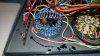
Finally got the resistors and the pot in and assembled over the last couple days.
20210305_172427.jpg
20210305_172414.jpg

I decided to disassemble the old pot and see how bad it was. I didn't realize it was a rheostat on both halves and not carbon tracks. I discovered why the 50k section went dead about 1/2 way through its range and I couldn't get continuity from end to end.

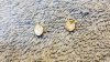
Here you can just barely see a couple of the wires of the rheostat winding broken!
20210305_202628.jpg

This is the 5k section and you can see the winding is much thicker...
20210305_202934.jpg

Here's both halves compared to each other.
20210305_203016.jpg

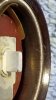
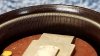
So once I got it all back together I discovered that while trying to calibrate it that the throw switch for Gm was intermittent. I had to go in and disassemble the switch. It was tricky doing it in place because it was rivetted to the chassis but I managed to get it cleaned and lubed in place.

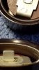
Here's the slide contacts after being wiped off (but before chemical cleaning)...
20210307_141434.jpg

Here's the pole contacts before cleaning....
20210307_141442.jpg

Here's the pole contacts all cleaned, polished, deoxited, and drying before getting lubed with dielectric grease...
20210307_144006.jpg
 
Nice. If you switch is busted, I may have an extra one, but not a push button type but lock and push to unlock (nice for longer gm test).
But my buttons look different than yours.
20181214_153208.jpg
 
Nice. If you switch is busted, I may have an extra one, but not a push button type but lock and push to unlock (nice for longer gm test).
But my buttons look different than yours.
View attachment 2156026

I may have to take you up on that.

Unfortunately, even after cleaning and lubing my switch it's still not working. When I try and do a Gm test the meter needle will move at some point during the throw of the switch. But it only jumps a little and then settles back to "0". If I try and slide the switch slowly I can almost get it to read. Only on 1 or 2 occasions have I actually managed to slide to and hold it in the position where I get a reading. Obviously this is not easily or consistently repeatable. This is the same behavior from before I put in the new board, so I am generally confident that it's the switch.

What's frustrating is that after I cleaned it I got good continuity readings from all the external connections on the switch as I moved it through it's motions.

My switch has 3 poles. I notice on yours there is no large resistor soldered to the switch (R45 I believe).
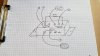
Here is a sketch of the connections.
20210311_090147.jpg

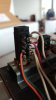
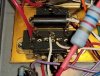
Here's a closeup of the switch in situ... ignore the large banded resistor on the right (that's the temp 1.6k for calibrating the Gm).
20210305_172427.jpg
 
Back
Top Bottom