• The move to the new server is done. There are some software and database maintenance updates in process. This has us passing the hat around to help out. We appreciate any donations. Seriously, even a dollar helps. The payment page may be found here - https://www.audiokarma.org/support.html

Upgrading the RCA RS177A - RS177J Console Amps: Three Stages of Mod Recipes

wparks

AK Subscriber
Subscriber
RCA_RS177A_Stock.jpg

Upgrading the RCA RS177A - RS177J Console Amp: Three Stages of Mod Recipes


What's wrong with the RS-177? (A LOT!): A Convenient Index to Problems and Solutions:

Filaments and Tubes Running WAY Too Hot:
> Stage 0: Buck the Primary! DO THIS FIRST!

A Severe Lack of Gain:
> Quick Overview of How Your Amplifier Works

> Increasing Gain by Hacking the 6CG7 Cathode:
> Stage 1: The Easy "Cathode Hack" Recipe

> Increasing Gain by converting to the 12AX7:
> Stage 2: The Best, CORRECT and Complete 12AX7 Mod Recipe (Part 1)
> Stage 2: The Best, CORRECT and Complete 12AX7 Mod Recipe (Part 2)

Bad Crossover Notch Distortion and a Starving Output Stage:
> Stage 3: Conversion to Enhanced Fixed Bias (EFB™) (Part 1)
> Stage 3: Conversion to Enhanced Fixed Bias (EFB™) (Part 2)

== WARNING == Vacuum tube amplifiers have =LETHAL= high voltages. If you are not 100% confident in your understanding of the danger and your ability to work safely with this equipment, please DO NOT attempt any of these modifications and instead refer them to a skilled technician.


A short foreword:

Since joining Audiokarma, I been a huge fan of the work of Dave Gillespie ( @dcgillespie ). He is a mentor, a skilled teacher to be followed and to learn from his examples. I have enjoyed tremendously his work on affordable Magnavox console amplifiers- upgrading them from rough raw pulls plagued with the many shortcomings and miserly design choices, into the robust stand-alone high fidelity components with performance approaching a much higher pedigree.Whether it's the legendary 6BQ5 8600 DGSE-1, the 6V6 push-pull 8800, and the 6BQ5 push-pull 9300 (and many others) his basic approach is the same: Illustrate clearly the problems of the "before" circuit, then design a masterful set of improvements while striving to preserve the original character, then fully characterize and document the "after" circuit, presenting a complete final recipe and discussion easy for most everyone to follow. This is incredibly useful to both those seeking a quick recipe to upgrade their one example, and for those more broadly seeking a valuable master class in common problems and expert approaches to correct them.

It is my intention to pay homage to Dave's work by emulating his examples here- To thoroughly analyze, upgrade and document the RCA RS177x console amp. This is nothing new, this amp has been reworked by many people just as with the Magnavox amplifiers- but here I intend to present a more thorough treatment, with in-depth explanations, multiple "stages" of upgrade recipes, with sufficient clarity and quality so as to be both easy to follow and hopefully provide the preeminent complete go-to rebuild guide for this amplifier. I have very big shoes to fill indeed.

I lucked into the opportunity to do this design and upgrade work with an RS177H model that I was hired to rebuild. My customer was extremely patient as I took the time to develop, characterize, and document the various stages of upgrade, and I say Thank You sincerely for that opportunity.

Upgrading the RCA RS177A - RS177J Console Amp: Three Stages of Mod Recipes​


One amp, Sooo Many Variations . . .

The RCA RS-177 (RS177) went through at least 5 or 6 design iterations- From the RS-177A to at least the RS-177J, with only minor differences between them. This power amplifier chassis was used across a range of RCA console models, being paired with either a simple pre-amp tone control chassis, or a full AM/FM radio tuner with or without record player with a lot of different features. In the RS-177A, the power transformer does not have the extra 6.3V filament winding that the later versions do, and the output transformers have two speaker output taps- A yellow wire that is 4 ohms, and a green wire that is 8 ohms. In the RS-177B, the power transformer had two 6.3V filament windings, the power supply used a series choke instead of 100 ohm dropping resistor, and the output transformers also had 4 and 8 ohm taps. Later variants of the RS-177 chassis generally have two 6.3V windings, and output transformers with only one output tap- the yellow one, which is still 4 ohms (they were at least consistent there). The last version, the J model, appears to have used those potted PEC modules in the pre-amp, and you will find it desirable to remove them and replace them with higher quality components following the mod recipes. All modification recipes here will use the 4 ohm yellow tap for negative feedback and the output zobel network, so the recipes should be generally applicable to all versions of output transformer, but if you are lucky enough to have an "A" or "B" version you are fortunate to be able to drive speakers on the 8 ohm tap if you desire.

Pardon the gratuitous strings for search hits: This thread applies to the following models: RCA RS-177, RCA RS177, RS-177A, RS177A, RS-177B, RS177B, RS-177C, RS177C, RS-177D, RS177D, RS-177E, RS177E, RS-177F, RS177F, RS-177G, RS177G, RS-177H, RS177H, RS-177I, RS177I, RS-177J, RS177J, so there.

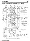
Some various stock schematics of several of the versions are posted below.
 

Attachments

  • RCA_RS177A.jpg
    RCA_RS177A.jpg
    111.6 KB · Views: 9
  • RCA_RS177F_original_RCA_Sch.jpg
    RCA_RS177F_original_RCA_Sch.jpg
    127.3 KB · Views: 9
  • RCA_RS177F_original_Sams_Sch.gif
    RCA_RS177F_original_Sams_Sch.gif
    100.2 KB · Views: 4
  • RCA_RS-177J_Snippet.jpg
    RCA_RS-177J_Snippet.jpg
    66.6 KB · Views: 3
Last edited:
Register to hide this ad

Filaments and Tubes Running WAY Too Hot: Stage 0: Buck The Primary! DO THIS FIRST!​


This is Stage 0 of the mod recipes because EVERYONE should do this whether or not you do ANYTHING else. All mod recipes and results will assume that this very necessary hack has been performed first.

Like any appliance from the 1960's this amp was designed for a 115V to 117V AC wall voltage- by running at the higher modern voltage of 120V to 124V AC, both the high voltage power supply and the tube filaments are all running WAY too high. This amp also originally supplied filament and high voltage power to the tuner or pre-amp chassis, and with that chassis now absent, the more lightly loaded power transformer is providing even higher voltage than before. To make things worse, in order to keep crossover notch distortion to a minimum, (discussed in detail later in the thread) the designers cranked the bias current of the output tubes up until they were running at the full maximum 12W design center plate power limit (when at the correct wall voltage and with tuner attached). Now, all of these conditions have compounded, so if you try to run this amp stand-alone without the following modifications, your expensive 6BQ5 output tubes are =ROASTING= at 15 Watts plate dissipation and with higher filament voltage!! Don't expect your expensive output tubes to last very long under these conditions- maybe a few months?

The Very Easy Solution: Buck the Power Transformer Primary​

For the RS177 versions after the "A" model you're in luck- This amp chassis was also the power supply for tuner/pre-amp so the power transformer has a second, now unused 6.3V filament winding. This is the blue and blue/yellow wires that went only to the white square molex connector. The overall idea is that this spare winding is connected in series (NOT parallel!) with the power transformer primary, and if the polarity is correct, it will buck (lower) the 120V+ wall voltage down almost perfectly to the original 115-117V. (The opposite polarity raises the voltage.)

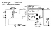
For the RS177 "A" version which does not have the second 6.3V filament winding you can still buck the primary, you just need to add a small separate 6.3V filament transformer under the chassis. I recommend a very inexpensive 4 Amp transformer such as the Hammond 166N6 or similar- it just needs to be rated for a higher filament current than the ~2-3A fuse for the amplifier. Just connect it up according to the "A" version diagram below (left), but since both 6.3V output wires are green, you can't tell which is which, so you will need to try each polarity to find the one that results in the lower voltage. For any model, when finding the correct polarity for this 6.3V winding, it's best to remove ALL of the tubes, and do the measurements the main 6.3V AC filament voltage of the original stock circuit first. That way you can tell if the new voltage is higher or lower than stock with the polarity you are testing.

(LEFT) Bucking RCA models without extra filament winding, (RIGHT) Later models with the extra winding.

RCA_RS177A_Primary_Buck_Schematic.jpg RCA_RS177_Later_Models_Primary_Buck_Schematic.jpg

For later models: The wire colors I show in the diagram are for this later RS177 model I'm working on, but these colors may not be consistent, so double check your transformer. You may have to try one polarity of the 6.3V winding, measure, then the other. You want the polarity that gives you lowest filament voltage. On the H model I found the lower voltage when I spliced the blue-yellow filament lead to the solid black of the power transformer primary. The path of the AC circuit then forms the following loop: in one side of the line cord, through the fuse, through the switch, then into the black-red primary lead and through the primary, back out on the solid black primary lead spliced into the blue-yellow 6.3V filament lead, through the filament winding and out on the solid blue 6.3V filament lead and spliced into the other side of the line cord. This is what is shown in the diagram above. Check your work carefully, and do the initial power-on test on a dim bulb tester to make sure you have not created a short circuit. Once you do this, all voltages on the amplifier with tubes in and loaded will fall into spec- On this one, the 5V rectifier filament now runs 5.03V, the 6.3V filament ran 6.4V, and the high voltage at the rectifier cathode was at 366V, down from the previous 389V. (Still slightly higher than the 360V from the schematic, because there is no tuner or pre-amp load.) All mods, discussions, and measurements that follow assume that this mod to buck the primary has been installed.
 
Last edited:

A Severe Lack Of Gain:​


In these consoles, RCA used two separate chassis for the power amp and the tuner/pre-amp. In the case of the RS177x, it is unfortunate that all of the audio voltage gain of the system was actually in the tuner/pre-amp- Typically using a 6CG7 triode gain stage to drive signal into the tone and volume controls, then a second 6CG7 stage to amplify the audio signal to a large voltage amplitude and drive it through a cable over to the power amp. The power amplifier by itself has almost no net voltage gain- it is actually unity gain (gain of 1). This means that the voltage driven out to the speakers is the same amplitude voltage as the signal level driven into the input, (but at a much higher current obviously). Consider that most modern audio sources only output about 1-2 Vrms (line level), and for maximum power into 4 ohm speakers you need roughly 8 Vrms. So, without a pre-amp with a VERY high output you are limited to disappointingly low volume levels. You would need an amp just to drive this amp!

The most common change to increase the gain of this amplifier is to convert the front end from the very low gain (mu=20) 6CG7/6FQ7 tube to the high gain (mu=100) 12AX7 that allows reuse of the 9-pin sockets (after rewiring the filaments and removing ground from pin 9!). This is the mod recipe that was presented somewhat incompletely by Blueglow in a popular YouTube video that unfortunately seems to have become the "go-to" recipe for this amplifier. Converting to the 12AX7 will undoubtedly provide the highest potential increase in performance, but unfortunately the Blueglow video and recipe is an incomplete conversion with poor documentation that will cause some serious problems. I'll discuss this in more detail when I present the correct and complete 12AX7 conversion in the next mod "stage". But first I have a very simple mod that will get you MOST of the gain you are looking for, achieve spectacular and beautiful results, using the original tube lineup and with only a couple of component changes (assuming you have bucked the primary discussed above!)

But First! A Quick Overview into How the RS177x Works:​

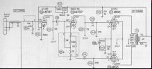
If understanding how the circuit works is not interesting to you, just skip down to the "Increasing Gain by Hacking the Cathode" portion below. Consider the diagram of one channel shown below. The first 6FQ7/6CG7 triode (V201A) is a basic voltage amplifier, a triode in common emitter, providing most of the open-loop signal gain of the amplifier. Signal enters through the grid stopper R231 (330K) to the grid (pin 2). R201 is the grid return holding the grid lightly to DC ground. R222 is the 82K plate resistor, and R208 the 8.2K cathode resistor. The plate and cathode resistor set the operating point (bias) of the triode and set it's amplifying gain. These value cathode and plate resistor chokes the bias current on this triode down quite a bit- This tube normally likes to flow 5-10mA but here it is down at only 2mA. At this bias current the 8.2K cathode resistor then purposefully raises the cathode up to about 6 volts- pretty high for an input triode. This rather large cathode resistor also results in low gain for this triode stage due to a form of local negative feedback called cathode degeneration. For a typical high gain amplifier these design choices seem odd, but keep in mind that in these models the tuner/pre-amp is driving out a very large signal, up to 8Vrms which is 22V peak to peak into this triode. The 6CG7/6FQ7 is designed to handle positive grid voltages (class A2 operation) because it was originally designed as a horizontal and vertical deflection oscillator in televisions, so it is well suited for this role- the +6V on the cathode centers the operating point on the load line to enable the tube to handle such large grid voltage swings (from roughly -17V to +5V).

RCA_RS177_Stock_Channel_Schematic.jpg

The first triode passes along it's amplified output signal through C201, the .27uF coupling cap to the grid of the second 6FQ7/6CG7 triode (V201B) which is arranged as a split load or cathodyne phase inverter. This tube is also biased very lightly at about 2.5mA, but enough to enable fairly low resistance 27K/22K plate and cathode resistors (R204,R224), with about 60V at it's cathode and 225V at it's plate. This allows low output impedance and large voltage swings on both outputs, to drive the two mirror-opposite versions of the amplified signal through C202 and C203 into the grids of the two push-pull 6BQ5 output tubes. Note that the inverter plate load resistor is 27K (R224) and the effective cathode load resistor is the combined 24.7K (R203 + R204) since output is taken directly at the cathode. In a standard cathodyne phase inverter these two resistances would be identical. I presume that these imbalanced plate and cathode values were arrived at through production testing, to result in the lowest distortion using these output transformers in the actual product. There is also an unusual 22K resistor (R205) in series with the cathode output, likely to compensate for the cathode of the phase inverter having a much lower output impedance than the plate.

The R209 5.6K global feedback resistor and it's parallel C211 100pF frequency compensation cap bring the positive speaker output from the 4 ohm yellow tap back around to become a feedback input into the cathode of the first triode, thereby becoming a negative inverted input into the triode. The 5.6K feedback and the 8.2K cathode resistors form a voltage divider which determines the amount of this negative feedback signal that appears at the cathode. The amount of negative feedback signal (in dB) is subtracted from the amount of open loop (without feedback) gain of the amplifier. The advantage of this negative feedback is that it greatly reduces distortion, widens frequency bandwidth, and lowers output impedance (better damping and more bass control) by allowing the amplifier to correct for any error (difference) between the input and output signals of the amplifier.

From my measurements this amplifier has a closed loop gain (with negative feedback in place) of unity (1x, or 0dB). It actually has an open loop gain (with negative feedback disabled) of about 8.5x, or 18dB. This means that for a final closed loop gain of 0dB, the amount of negative feedback is equal to the amount of open loop gain, or about -18dB. That is a large amount of negative feedback for a console amplifier. (Many Magnavox console amplifiers run with only 11-12dB). It means that RCA is using really good stable output transformers, and they wanted this amplifier to have very wide bandwidth, with very low distortion. Lots of global negative feedback provides just that and indicates the pride that the RCA engineers took in the performance of this design.

This provides us with a huge opportunity! As mentioned, the gain of the first triode is set quite low by the 8.2K cathode resistor, and a very hefty amount (18dB) of global negative feedback is being applied, both of which greatly reduce the overall gain of this stock design. But this provides opportunity to easily increase the sensitivity while still using the existing tube lineup. We need only dial back the amount negative feedback, and increase slightly the gain of the existing 6FQ7/6CG7 triode tube- a very simple change indeed!
 
Last edited:

Increasing Gain by Hacking the Cathode​


If you just want the final recipe, skip down to that part. Otherwise, I'll explain how this works so you can customize the personality of your amp to your preference.

The gain of the first triode voltage amplifier is set by the AC value of cathode resistor and the plate resistor. If you use a capacitor to bypass part of all of a triode's cathode resistor (to decrease it's AC resistance), you increase the gain of the stage. If you do this while leaving the total amount of DC resistance in the cathode current path the same, it will leave the bias point (cathode voltage) the same. At least part of the cathode resistor should remain unbypassed, to provide a leg for the lower half of the negative feedback voltage divider, and giving a place to insert the feedback signal at the cathode. If you decrease the amount of this unbypassed cathode resistor leg, you simultaneously increase the open loop gain of the triode, while decreasing the amount of negative feedback by making that leg of the voltage divider smaller. Both work in the same direction to greatly increase the closed loop gain, and this is the direction we want to move in.

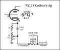
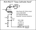
I created a simple jig that I could temporarily install in the corner of the chassis where the cathode and feedback resistors lived near the original speaker connectors. It was a ~3K fixed resistor, a 5K pot, and a 470uF bypass capacitor that would leave the total DC cathode resistance at about 8K to preserve the stock DC bias point, but also allow me to control how much of that cathode resistance was bypassed. A diagram of this jig is shown below. The lower portion of the pot "Rk" that was not bypassed and would control the amount of gain and feedback. With the pot wiper turned to the top, 3K was bypassed and Rk = 5K was unbypassed which provides only a modest increase in gain over the stock circuit. When turned to the other extreme the wiper was at ground and the full 8K was bypassed (so the AC resistance is zero), the feedback signal had no leg, so was safely shunted directly to ground and the amplifier would run at the full maximum open loop gain with no negative feedback at all.

RS177_Cathode_Hack_Jig.jpg

What I discovered is that the pot could be turned from one end to the other and in all cases the amplifier was completely stable and very well behaved. My goal with this experiment was to see if I could achieve a setting that enabled me to drive the amplifier to full output power with a 2Vrms signal (a reasonable high-ish line level), and still retain at least some negative feedback for good fidelity.

With the pot set to the top (Rk = 5K) it took a very large 6 Vrms signal to drive maximum power. At about midrange, about 4 Vrms. At about 1/4 position, it took about 2.4 Vrms. With the pot wiper all the way down to ground, running at maximum open loop gain, it took less than 1 Vrms, but here there was no feedback at all so the distortion was high and it sounded bloated and boomy. So, I set the input to the desired 2.0 Vrms goal, found the pot position that gave exactly maximum output power before clipping, then unsoldered one leg of the pot and measured it. The magic final recipe was 7.5K bypassed, with Rk = 560 ohms un-byassed leg to set both gain and feedback to acceptable levels leaving all other components as is. The above jig is very simple to build, and if you are interested it provides you with an opportunity to tune your own favored cathode hack setting, balancing input sensitivity versus amount of feedback. It was very interesting how much the personality of the amplifier changed at the different settings.

Stage 1: The Easy "Cathode Hack" Recipe​


RS177_Cathode_Hack.jpg RCA_RS177_Cathode_Hack_Channel_Highlight_Schematic.jpg

This simple hack is so quick and easy I am really surprised that I have not seen this done with this amplifier before. Overall sensitivity and test results with this change are quite excellent. I could now drive maximum power into 4 ohm load (just before clipping) with a 1.9 Vrms input signal, which is a high-ish line-level. Closed loop gain at 1 Watt output was 5.0X = 14dB. Open loop gain at 1 watt was 12.55X = 22dB, so with this mod recipe the amp is now running with (22dB - 14dB) = 8dB global negative feedback. Not a bad place to be- very warm and lively but great fidelity.

Frequency response at 1 Watt was excellent- within 1dB from 12Hz up to 60kHz, within 0.5dB from 20Hz-50kHz. Power Bandwidth (Max Out - 1dB) was also quite excellent- within 1dB from 25Hz up to the same 60kHz.

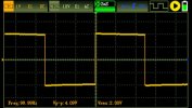
Square wave transient response (also into 1 Watt) was absolutely beautiful, with the smallest little text-book overshoot and resolution, with a fast rise and fall rate, flat plateau, no sign of under-damped response, just could not look better.

16.jpg

Listening Test: My primary concern was whether the amplifier would be sensitive enough with common sources while running 8 ohm speakers (with the RS177's stock 4 ohm output transformers). The test area was a medium size living room. My test speakers are Boston Acoustics CR77, decent 89dB two-way 8-ohm large bookshelf speakers. My small cheap DAP that tends to have a low output level was somewhat disappointing as I had to use maximum volume, but it still provided a nice room filling "lively but still relaxing" volume level.

When I kicked it up a notch with my Denon DCD-425 CD player, which has a standard fixed 2Vrms max output level and a passive line stage I was quite happy- With the attenuator at about 50% the volume was louder than with the DAP at max, so the room was now filled with a solid but still comfortable "robust listening" volume that was still plenty loud enough to hear easily in the next room. As I rolled the volume control up to about the 75% mark, the volume was now quite loud- not rattling the windows but more of a "party" volume- louder than one would want to have a conversation over etc, and I could just begin to hear an audible increase in the amount of distortion that told me if I pushed it too much harder it would not sound as nice.

With the reduced amount of negative feedback in this mod, the amplifier was extremely pleasant and well behaved. It was certainly warmer, with a very solid and enjoyable bass presence, and mid through the high end was very lively, rich, and expressive, very well detailed, and more organic and "enhanced" if you will, than many of my more accurate high feedback amplifiers. Overall it was very enjoyable, not at all fatiguing, and I am certain that most will be really happy with the sound of this mod. Considering the very high quality results for very little effort, I think some will choose to stop here, well satisfied. But I must continue on . . .
 
Last edited:

Increasing Gain, Stage 2: The Correct, Best, and Complete 12AX7 Mod Recipe (Part 1)​

Why convert to 12AX7?​

When combined with bucking the primary, the easy "cathode hack" is the most simple mod for better sensitivity for the least effort while not intending to do a major rebuild. However it leaves a lot of performance on the table, and may not make sense to do if you intend to completely rebuild the amp with new components anyway. The motivation to upgrade to the higher gain 12AX7 is to increase the sensitivity of the amplifier to work well with all possible audio sources while at the same time continuing to use the robust -18dB of global negative feedback as the original low gain design. With the excellent output transformers RCA used in these models, that level of negative feedback will provide a most excellent performance- super wide, flat frequency bandwidth, lower output impedance (that provides tighter well controlled bass through better damping and excellent dynamic response) as well as very low levels of distortion. I dare say the complete 12AX7 upgrade recipe I present here, especially if combined with the later "stage 3" upgrade to Enhanced Fixed Bias will allow this chassis to enter credibly a more elite class, punching way above it's weight for what began as a lowly console amplifier.

What's wrong with the Blueglow Mod Recipe?​

Conversion to the 12AX7 tube is not a "quick and dirty" mod- several other parts of the design must be adjusted at the same time. The major problem with this mod recipe is that it does not consider what happens to the 6BQ5 screen voltage and resulting power draw. If you pull an amp out of a console and just do this mod as presented, you frankly risk red-plating your output tubes- if not, you will certainly be burning them away rapidly like cheap cigarettes.

There are a combination of factors that compound to create this problem. As I mentioned before, the RCA designers (while using 115V and with the load of the tuner chassis) intentionally cranked up the 6BQ5 bias currents until the plates were running at the datasheet maximum of 12W to minimize the effect of crossover notch distortion. Now decades later, power this same console on modern 120V wall voltage (it's 123V where I live) and now the output tubes are pulling even more bias current AND the filaments are running hotter. Now, take away the tuner chassis, with it's filament and high voltage load, and voltages are running even higher. From my measurements, the output tubes in this state are now running at 15 watts plate dissipation with high filaments. Ouch. =But it gets worse= Now, remove 7mA or so from the pre-amp supply by switching from the 6CG7/6FQ7 to the lower current 12AX7 tubes, and the drop in current will now cause the 6BQ5 screen voltage to run at least 15V higher than before. This increase in screen voltage dramatically increases the bias current further. If the 6BQ5 cathode resistors have drifted down at all or are at the low end of tolerance, it's even worse. I participated in an AK user's build thread that was implementing the Blueglow mod, and DID have a set of tubes red-plating. Others just live with the silent tube killer without even knowing it. Therefore, any conversion to 12AX7 MUST also include at a minimum bucking the primary, =AND= increasing the 6BQ5 cathode resistors to keep the bias currents to a safe value that is consistent with your overall design goals and below the 12W plate limit.

The 12AX7 mod design I present here is correct in the sense that it addresses all of these issues. It will provide a well documented recipe that is relatively easy to follow, and gives you an amplifier that will provide stellar performance. I call this the best recipe, because I set the bar very high for performance and it would be difficult to achieve better. My overall goal of this design was to increase to 20dB (10X) of closed loop gain which will give you the sensitivity you need to drive maximum power with roughly 1 Vrms of input signal (line level). I also wanted to take full advantage of these high quality output transformers and use somewhere close to the original -18dB of global negative feedback to preserve the excellent bandwidth and low distortion of the original amplifier, meaning I need an open loop gain of around 75X or around 38dB. I wanted the amp to run relatively cool, provide for a long tube lifespan, yet achieve good maximum output power- Everything you would want and expect from a high fidelity stand-alone amplifier.

Redesigned Channel​

First, please note that the 12AX7 connects the filaments differently than the 6CG7/6FQ7- The filament connections to the two sockets will need to be changed, and the ground shield connections to pin 9 will have to be removed, as they are no longer needed. For the 12AX7 sockets, one side of the filament supply will connect to pins 4 and 5 tied together, and the other side of the filament supply connects to pin 9. (This runs the two filaments in parallel for a 6.3V supply).

12AX7_Pinout_Bottom_View.jpg

The recipe begins with the diagram below of one channel. Because the 12AX7 conversion significantly increases the gain of the amplifier, more attention must be paid to stability and frequency limiting in order to prevent oscillation. The first additions that should be noted and considered required for this upgrade are a low-pass filter added to the audio inputs, and a zobel network added directly to the speaker outputs. The low pass filter at the input is comprised of the grid stopper R231 decreased from 330K to 33K, and the addition of a 47pF ceramic or silver mica capacitor right at the 12AX7 grid pin 2. The 47pF capacitor sums with and acts to stabilize the ~150pF of Miller capacitance looking into the grid to guarantee we are rolling off input frequencies significantly above 20kHz. This has the added advantage of helping to block out RF noise from digital sources and switching power supplies. The zobel network right across the speaker output simply adds a 0.1uF ceramic/poly cap in series with the original 47 ohm 2W resistor that is already there. The 47 ohm resistor by itself helps ensure stability especially when no speakers are connected, but by itself it will needlessly steal output power at all frequencies. By adding the .1uF capacitor in series it will still ensure stability, while only absorbing power above about 35kHz, the higher frequencies that cause instability. These components are now shown directly across the speaker outputs (not to the ground bus), where they belong.

RCA_RS177x_Correct_12AX7_Mod_Stage2_Recipe_Channel.jpg

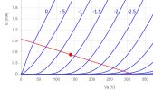
The carefully redesigned first triode gain stage is an elegant one- a design borrowed from the famous Magnavox 8600 using a "cathode pull-up and stabilization resistor", and optimized for linearity and low distortion. The 12AX7 triode is biased to draw 0.5mA with a 1.35V cathode voltage with a 330K plate resistor, creating an excellent high fidelity load line and operating point (shown below) that allows a large signal swing across a very linear region for this tube. This operating point is only possible with the assistance of the ingenious 150K pull-up resistor to supply. It allows a much smaller single cathode resistor (only 560 ohms) for high gain without fitting multiple resistors and large bypass capacitors that can couple, phase shift, fail, and cause problems. It also behaves more like fixed bias to greatly stabilize the operating point of the 12AX7 by dumping several times the actual bias current down through the small cathode resistor, elevating cathode voltage while minimizing change due to tube strength. This will ensure a stable operating point while rolling through different flavors of 12AX7 tubes and through aging. The nice elevated cathode voltage moves the operating point farther away from the saturation region (near 0V grid) allowing less distortion even for larger input signal amplitudes. The 330K plate resistor in concert with the 560 ohm cathode resistor were chosen through careful iterative testing of the actual design, to give the optimal amount of overall open loop gain of around 37dB.

Stage2_12AX7_Bias_Point.jpg

The split load or cathodyne phase inverter (the second triode) was optimized for the 12AX7 tube (something else not done in the Blueglow mod). The carefully matched plate and cathode load resistors (R204,R224) were increased from 27K to 47K, and the 22K series resistor (R205) removed, so the lower cathode output is now taken directly from the top of the cathode load resistor. The bias resistor (R203) was decreased from 2.7K to 1.2K to bias the triode to 1.3mA and ensure liberal swing range to cleanly drive the 6BQ5 outputs to maximum power. The really large value coupling capacitors (C201,C202,C203) were kept at 0.27uF to preserve the original bass response, and by eliminating that bypass cap across part of the first triode cathode leg we no longer have to fear low frequency instability due to phase shift. I prefer to use polypropylene coupling capacitors over polyester for the best transparency. (The Illinois MPW series are quite good and very inexpensive.) Since the output stage is at this point is still cathode biased with R229, the two 6BQ5 grid return resistors (R206,R207) remain for now at 470K. For fixed bias or with the EFB™ "stage 3" mod offered later, these have to be reduced to under 300K per datasheet for stability.
 
Last edited:

Stage 2: The Best, CORRECT and Complete 12AX7 Mod Recipe (Part 2)​

Output Stage Biasing​

As mentioned earlier, to prevent your output tubes from cooking away you really must buck the primary of the power transformer to keep the filament voltages in line, and you must re-bias the output tubes to compensate for the higher screen supply voltage to reduce the bias currents and keep the 6BQ5 plate power under the 12W limit. Unless you switch to Enhanced Fixed Bias (EFB™) covered in the next mod stage, the output power level at which crossover notch distortion appears will be a factor in deciding how much bias current to use here. At a low bias current, the tubes run cooler, but the notch appears earlier at a lower output power. RCA set this cathode bias current to about 40mA, operating the plates right at the 12W limit, so that the crossover notch did not appear until already near maximum power at the edge of clipping, effectively hiding it. If you are curious about what the crossover notch looks like, Dave G. has a great scope shot here (lower trace) in his great post #31 of the 9300 thread here.)

With my test amplifier configured with a bucked primary, and the conversion to the above 12AX7 recipe completed, I was able to test different cathode bias resistor (R229,230) values and observe the current and appearance of the crossover notch.

At R229/230 = 220 ohms, bias current = 31mA, plate power = 9W (tame) and notch appeared WELL BEFORE clipping.
At R229/230 = 200 ohms, bias current = 33mA, plate power = 10W (safe) and notch appeared later, but still before clipping.
At R229/230 = 180 ohms, bias current = 36mA, plate power = 11W (optimal) and notch appeared pretty late, just before clipping.

Of course, I could do as RCA did and pick a lower resistance to run the full 40mA to run the tubes at the full 12W limit, and it still won't be the stock 130 ohms because of the higher screen voltage. But, I have never liked running output tubes at the full rated design center power limit. By backing off to even 90% of the limit tube life will be prolonged with very little downside- the crossover notch at 36mA just starts to appear at the onset of clipping, when distortion is already rising from squash anyway, so seems like a good trade-off. For this reason, I have settled on 180 ohms as the optimal per channel cathode resistor for this recipe. While you are in there, be sure to upgrade the cathode bypass capacitors across the two cathode resistors- The stock design used a very low 20uF way over in the noisy can, and this can easily be upgraded to 100uF caps right across each cathode resistor. I like to use 50V or 100V capacitors, as the larger size handles the current better and will be less likely to dry out in this hot environment.

The 12AX7 conversion recipe does not require any changes to the power supply (except bucking the primary). However, a really nice upgrade here if yours does not already have it is to swap the 100 ohm 10W dropping resistor with a Hammond 156R choke. This small 1.5H 200mA choke is easy to fit under the chassis and has a series resistance of 56 ohms, so will result in slightly higher voltage and has much better filtering. This option is drawn into the final Stage 2 12AX7 mod recipe schematic below.

The feedback resistor R209/219 was adjusted to 6800 ohms to set the desired sensitivity and amount of feedback based upon measurements of open and closed-loop gains. The feedback compensation capacitors C211/212 were adjusted to find the flattest high frequency response, and the original 100pF value was confirmed as optimal. (A better resolution .pdf of this schematic is attached below.)

RCA_RS177x_Correct_12AX7_Mod_Stage2_Recipe.jpg


Test Results:​


With the test amplifier built to the above schematic using the power supply choke option, 180 ohm bias resistors with 100uF across them, the performance of the amplifier was now quite excellent.

Voltages:
Measured voltages are indicated on the schematic. With bucked primary, the filaments are now correct: Rectifier: 5.03V Audio: 6.41V

Maximum Power:
Measured with both channels driven into rated load, just before clipping, 1kHz sine
4 ohm load: 14.0 Watts (Crossover notch now starts to appear at about 12 Watts)
8 ohm load: 11.5 Watts

Sensitivity:
Maximum power is now achieved with an 860 mV (.860V) rms input.
This is now an easy to drive amplifier with any line level source, pre-amp or line stage.

Gain and Feedback:
Open loop gain is now 74X or 37dB, Closed loop gain is now 10X or 20dB, so Global Negative Feedback is now (37 - 20) = 17dB
This 12AX7 swap has achieved the desired goal- providing greatly increased sensitivity while preserving the stock amount of negative feedback.

Transient Response:
The 10kHz square wave response driven at 1 Watt into rated 4 ohm load (left) could not be more ideal or beautiful considering the high gain and large amount of negative feedback. Fast and symmetrical rise and fall times, just the ideal amount of slight overshoot with very fast resolution, leaving a beautifully flat plateau. These RCA output transformers are quite excellent in their winding, exhibiting very little resonant tendency. Similar test at 100Hz (right) indicates very little ramp with these large coupling capacitors, and should provide a deep rich bass. This amp is also completely stable with no speaker load attached.

1.jpg 4.jpg

Frequency Response and Power Bandwidth:
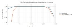
Frequency response was tested at 1 Watt, and Power Bandwidth at maximum power minus 1dB. Both results confirm the excellent construction of these output transformers. The pass band is very flat out to the designed roll-off as determined by the input low pass and output zobel network designed to roll off in the 30kHz range to ensure excellent stability despite the high gain and large amount of negative feedback. The bass performance as expected is excellent. At a 1 Watt output level, output is still within 1dB of flat even at 10Hz, with that waveform looking only slightly bent. When both channels are driven at max power minus 1 dB (12.5W) output is only down by 1dB at 30Hz, and down 3dB at 20Hz. Not bad for a console amplifier! A warning perhaps, that if you are intending to use this amplifier with a turntable and you experience problems with rumble causing your bass drivers to flutter or breath, you may want to employ a passive RC high pass rumble filter into the input of the amplifier.

Frequency Response at 1W: 10Hz - 50kHz within 1dB
Power Bandwidth (Max-1dB): 30Hz - 40kHz within 1dB

RS177x_Stage_2_Bandwidth_PWRBW.jpg
 

Attachments

Last edited:

Stage 3: The Conversion to Enhanced Fixed Bias (EFB™) (Part 1)​


We have vastly improved the gain and performance of the front end of this amplifier, which is now on par with the best of vintage tube audio. The next logical step in the transformation of the amazing RS177x amplifier is to now significantly improve the output stage. This last mod will not only completely eliminate the evil crossover notch distortion, it will dramatically improve efficiency, increase output power, and decrease distortion.

With traditional self-biasing using a cathode resistor under the output tubes, the operating point of the stage can shift dramatically in the transition from idle to maximum power because of an increase in screen current. This increase is worse for pure pentodes like the 6BQ5 or EL34 than with the better controlled beam tetrodes like the 6V6 or 6L6 family. This increasing screen current causes the cathode voltage to rise, decreasing the bias current, working to starving the output tubes. This starvation will begin to cause both output tubes to momentarily turn all the way off as they cross over the center point, creating the crossover notch. This increase in screen current will also cause the screen supply voltage to sag, which also significantly decreases output power. Despite these problems, self biasing is still very common because it is simple, cheap, and provides a flexible self-adjusting "good enough" operating point across variation in tube strength and age, favoring adaptability over optimal performance at higher output levels.

One strategy for overcoming the shift in operating point is to use traditional fixed bias. In this scheme, the output tube cathodes are grounded, and grids are held negative with a fixed (but adjustable) regulated voltage. This will provide increased output power and lower distortion, and the now rigidly fixed grid-cathode voltage completely eliminates the starvation that creates the crossover notch distortion. However, the screen supply will still sag significantly at high output power levels, so the operating point will still change more than desired. Regulating the screen voltage will provide further improvement, but introduces additional complexity into the design and is ultimately only partially effective. Dave Gillespie provides and excellent explanation of all of this and the benefits of the Enhanced Fixed Bias (EFB™) circuit he developed to address these problems in Dynaco amplifiers in his excellent build thread for the 6BQ5 push-pull Magnavox 9300, which was a major inspiration for my work here with the RS177x.

Enhanced Fixed Bias is more simple to implement than a separate negative grid bias voltage plus regulated screen supply, and is ultimately more effective. EFB instead provides a regulated positive voltage to the output cathodes, so you get most of the mentioned advantages of fixed biasing, but it goes a step further. The "Enhanced" part of EFB is that the regulated cathode voltage is now referenced to the screen voltage. Now, as the screen supply voltage sags at high power the regulator decreases the cathode voltage in unison, "pressing on the gas" to increase the drive current to compensate, maintaining a much more fixed operating point. The result of this regulation is increased output power at decreased distortion.

A great side effect of EFB is that when the amplifier is not working hard and the screen voltage is higher, the bias current is reduced allowing the amplifier to idle at a much lower power level. Output tube bias currents no longer need to run at a constant high level to avoid the starvation. Rather than running 40mA per 6BQ5, the 9300 with EFB referenced above idles with only 22mA! per 6BQ5. The result is the transformer, tubes, everything runs cooler, the tubes last a LOT longer, and the amplifier is more efficient. Yet, when high output power is called for, the amplifier roars to life, and can now direct much more power to the output than previously possible. It really is a dramatic improvement.

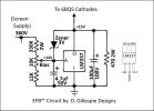
The core of the EFB regulator is shown below. It centers around the LM337 adjustable negative voltage regulator. Why negative? Because a negative voltage regulator sinks rather than sources current, and holds the output at a higher voltage than the input- just what we need for a cathode. In this case, the input is actually ground, and the output will be held at an adjustable voltage around +15V. The metal tab of the TO-220 package and center pin are both IN, and are connected to ground. The regulator is easily mounted to the metal chassis, and does not need to be insulated as the tab is ground, but some heat-sink compound is required. The supply voltage for the regulator adjustment is taken from the 360V screen supply. The 330K, 10K bias adjust pot and 12K on the left form a voltage divider from 360V to ground, providing around 14V at the pot center wiper and ADJ pin. This ADJ voltage will now change as the screen voltage does, providing the "enhanced" part. When you wire this, arrange the pot connections so when the pot is rotated clockwise the wiper moves down towards the 12K and away from the 330K. This will decrease cathode voltage (turning up bias current) when turned clockwise to increase so it will feel intuitive.

EFB_Circuit_Detail.jpg

The 4.7uF provides some smoothing for the adjust voltage. The 3V Zener protection-diode from OUT to ADJ (with band facing ADJ) was added by Dave Gillespie in a Nov. 2025 update to "bullet proof" the regulator from some rare failures seen now and again in a few builds.

The 100uF connecting from OUT to GND is the typical cathode bypass capacitor to ensure the cathodes are at a solid AC ground. 100uF is used for low frequency response, and I like to use 50V to 100V rating to ensure the capacitor is large and will be robust and reliable for years to come. The 470 ohm 2W resistor is just to take a little load off of the regulator by sinking part of the cathode current, helping ensure that the regulator runs cooler. This entire circuit is very easy to build on a single 6-lug terminal strip, and I may have a sketch of an easy layout a bit later.
 
Last edited:

Stage 3: The Conversion to Enhanced Fixed Bias (EFB™) (Part 2)​


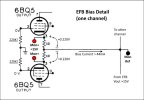
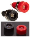
Below is a detail of how the bias current monitoring works. The EFB output provides the ≈15V cathode voltage that is connected to the single black "Mon Ref" monitor point. The actual voltage measured from Mon Ref to ground will depend upon the strength of your 6BQ5 output tubes- for newer hotter tubes this will be higher, like 16V, and for older worn tubes it will be lower, more like 14V or lower. In this design I have incorporated a total of five monitor points- one black common "Mon Ref" reference point, and four red "Mon+" points, one for each 6BQ5 output tube. This is not overkill- I =highly= recommend per-tube monitoring as it will allow you to actually match your own tubes into sets, arrange them for best in-channel matching, and verify the matching of often poorly matched quads of new output tubes. The ability to match your own tubes is a =huge= advantage compared to the cost of a few tip jacks and a couple of extra holes. If you use the little 2mm tip jacks they are really very easy to install and can be had very cheaply on Amazon, etc.

EFB_Cathode_Detail.jpg 2mm_Tip_Jack_Test_Points.jpg

The bias current flowing from each 6BQ5 cathode passes through it's own 10 ohm monitor resistor, dropping a small DC voltage across it. When the bias adjust is set so the voltage measured from a red test point to the center black reference equals 0.220V (220mV) the bias current for that tube is 22mA, the desired bias setpoint for this amplifier. The grids of the 6BQ5 tubes are held at ground through their individual grid return resistors, which take note, are now 220K instead of 470K as they were with self biasing. This is =required= for stability per datasheet. Since all four 6BQ5 tubes get the same DC cathode voltage, good performance requires the use of better matching tubes to keep the resulting cathode bias currents more or less equal. This bias setting will need to be adjusted for each different set of tubes, and re-adjusted every few months as the tubes age. When changing tubes, be sure to set the bias control for minimum before you power up, then after a few minutes dial it up to the desired level.

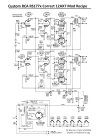
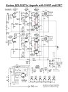
Below is the complete stage 3 schematic, incorporating both the "correct" 12AX7 front end upgrade, and the Enhanced Fixed Bias upgrade. Most of the schematic is the same as posted for the 12AX7 mod alone, except the 6BQ5 grid returns (R206/R207 and R216/R217) have been adjusted from 470K down to 220K as mentioned. The previously recommended power supply upgrade from the 100 ohm 10 W dropping resistor to the much better Hammond 156R 1.5H 200mA choke is now even more strongly advised with EFB. It is not very expensive, fits beautifully under the chassis near the power supply, increases the available B+ voltage at maximum power, and provides much better ripple rejection. A better resolution .pdf of the schematic is attached below.

RCA_RS177x_12AX7_plus_EFB_Mod_Stage3_Recipe.jpg


Test Results:​


The RS177H test amplifier was rebuilt to the above schematic with the complete 12AX7 front end, EFB, and power supply choke option. I had previously matched a reasonably good close set of tubes that were testing just above the datasheet plate current. The independent monitor points proved very useful- You will see that no matter how well a new set of tubes are matched, they will differ in each particular operating setting, and will drift apart as the tubes burn in. I adjusted the bias on this group of tubes so the lowest read 0.220V, indicating 22mA of cathode current for that tube, and arranged them for the best channel matching. The other three ran slightly higher than that one, which is just fine- 22mA is a pretty lean bias current so I consider this the minimum, but it works beautifully because of the EFB enhancement. All testing was performed under these conditions.

The improvement in performance over the non-EFB version was really quite dramatic.

Maximum Power
Measured with both channels driven into rated 4 ohm load, just before clipping, 1kHz sine
No EFB: 14.00 Watts (Crossover notch appears at 12 Watts, a bit before clipping)
W/ EFB: 15.25 Watts (Crossover notch is now =completely= gone.)

Sensitivity: Input voltage for Maximum Output
No EFB: 860mV, With EFB: 781mV rms - Just demonstrates higher output for less signal

High Voltage Power from Rectifier
Idle: No EFB: 57 Watts, With EFB: 42 Watts -Power transformer now idles 15 Watts cooler!
MaxP: No EFB: 71 Watts, With EFB: 76 Watts -But MORE power is supplied to the outputs when needed

6BQ5 Plate Dissipation
Idle: No EFB: 11 Watts, With EFB: 8 Watts -Outputs idle 30% cooler, so the tubes will last WAY longer
MaxP: No EFB: 12 Watts, With EFB: 13.6 Watts -Again, MORE power available to the outputs when needed

6BQ5 Screen Voltage
Idle: No EFB: 335V, With EFB: 359V -Screen voltage now idles 24V higher due to much lower bias current
MaxP: No EFB: 302V, With EFB: 268V
Previously, there was a 33V drop in screen voltage. With EFB the screen voltage drops an amazing 91V because the outputs are working that much harder. However, EFB still compensates, greatly correcting the operating point as cathode voltage shows next.

6BQ5 Cathode Voltage (lower voltage = more current)
Idle: No EFB: 13V, With EFB 15V -At idle the cathode voltage now runs 2V higher for a lower bias current.
MaxP: No EFB: 17V, With EFB 11V
-Notice the change in direction at maximum output- instead of the cathode voltage rising to 17V and starving the outputs, EFB leans in, dropping the cathode voltage to 11V to aggressively shift the operating point and increase current to drive the load harder.

So, with EFB, yes, maximum power is now higher, but that's not even the big headline here. The important difference is the regulation that is happening- With cathode resistor self bias the output tubes are getting pinched from both ends- as output power increase, screen voltage drops, and cathode voltage rises both acting to starve the drive current. This happens during every heavy bass passage, or dynamic swell in the music- the operating point is mushy- sagging dynamically, stealing bass, and significantly increasing distortion. With EFB regulation, the output drive current is increased in sync to counteract the sagging screen supply, resulting in a much more rigidly held operating point. The result is higher power, but more importantly, better transient response, with significantly lower distortion. From a DC power perspective, the entire power profile of the amplifier has changed to become much more efficient. The amp idles 30% cooler, the output tubes will last much longer basking at a relaxing 8W of plate dissipation, yet is able to direct even MORE output power when demanded. It's a remarkable improvement.
 

Attachments

Last edited:
Interesting. I just happen to have a RS177f sitting in my stash pile waiting to do something with it. Thanks for posting this!!
 
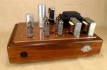
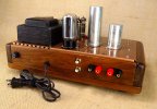
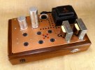
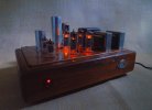
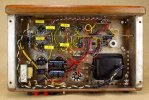
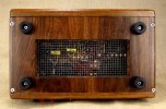
I wanted to conclude the first pass of this build thread with some glamour shots of my customer's finished amplifier. He had previously done the hard work of building the wooden wrap- I did the new hammer-tone paint and the complete rebuild- new sockets, caps, resistors, etc. How does it sound? Talk about beauty and the beast- She's both. Without a doubt the best amplifier I have had the pleasure to work with. I can't say enough about these RCA output transformers- They're just console transformers right? But RCA really knocked it out of the park- I have never seen a console amp with transformers this good- getting very low frequency performance (only down 1dB at 30Hz =at power=), and a barely existent resonant peak at like ~190kHz. With these transformers, the 12AX7 front end redesign, and Dave Gillespie's EFB back end, my customer now has something REALLY special.

Thank You for the opportunity to do this.

DSCN0070.JPG
 

Attachments

  • DSCN0075.JPG
    DSCN0075.JPG
    149.5 KB · Views: 22
  • DSCN0068.JPG
    DSCN0068.JPG
    167.6 KB · Views: 23
  • DSCN0059.JPG
    DSCN0059.JPG
    174.2 KB · Views: 22
  • DSCN0066.JPG
    DSCN0066.JPG
    181.2 KB · Views: 23
  • DSCN0078.JPG
    DSCN0078.JPG
    113.4 KB · Views: 23
Last edited:
Something else you may consider here is adding the EFB screen regulator portion. That will keep the screen voltage tracking better with plate voltage, which will likely reduce distortion further. The input for the LM337 would still be from the supply to the screens, but that would be the output of the MOSFET rather than R226. R226 would probably need to be bumped to maintain voltages at the 12ax7 stage since the screen current will no longer be present across it.

a measurement of voltage drop at idle vs full output power would be a good clue whether that makes sense. If the drop in % is similar to the screens as it is at the output transformer feed, its not going to help. The bigger the difference, the more improvement it will make.

Just a thought

otherwise nice writeup.
 
Thanks @gadget73 - You are right.
With EFB, the B+ dropped from 382V to 333V (-13.7%) idle to max, and the screens dropped 359V to 281V (-24%) so screen regulation would have cut that drop considerably. The EFB cathode regulation alone still performed remarkably well- I was quite amazed to see the cathodes decrease to 11V rather than increase to 17V under maximum power- watching EFB bear into the load like that was impressive.

There is a lot of Dave's work on other amps I have not yet digested- is there an example where he uses both cathode and screen EFB on a 6BQ5 PP? (probably really dumb question)

I only wish I had measured distortion in both cases. My setup for that is not very elegant right now, but I'm working on it.
 
Last edited:
yeah the bias shift with cathode bias AB amps is real. Also fair bet that you could idle it lower than the stock bias point and get or beat the stock THD performance. From discussions I'd had with Dave on this topic, basically all you have to do is wind it up close to full output, tweak the bias until you find the point where the distortion nulls, remove the input signal and see where it landed. One amp I did ended up at 11mA per-tube which is very low but thats where it works best with both EL84 and 6P15P types.

The Fisher SA-100 thread has the screen regulator portion, but that one is standard fixed bias. Offhand i can't think of one with the screen and cathode EFB but it should just be a matter of disconnecting the screens from the existing resistor and moving them to the output of the MOSFET. The EFB cathode regulator would remain connected to the screens so it will still track based on that voltage. On my long list of things to get back to is a 6L6 family amp that may get that treatment.
 
11mA! Holy cow!

I'd like to see how that goes with the 6L6 build.

I also really enjoyed @nerdorama's build on that Rowe amp. I'd like to try that. Screen EFB plus fixed biased (Since it's already there) is sure a winner.
 
@wparks
If/when you get to the Rowe maybe you can kibitz with me a bit on the signal grounding. I have a slight hum which only occurs when a line stage is connected. Dead quiet with shorting plugs so it’s got to be a ground loop, I assume. I reworked the audio ground system once with no noticeable effect. I might go back in and change to a larger gauge buss to see what happens.
 
Hey no problem - sounds great. Nice amp man. Makes me think seriously about using the original chassis yours turned out so nice! Wanting to try that JB weld and see how well it works. I read those posts on the noise, and was scratching my head. Maybe we can shake it out.
 
I know a lot of time and energy went into this thread. The RS177 has the potential to sound fantastic. A lot of valuable information here. Thank you for sharing all this information.
 
There is a lot of Dave's work on other amps I have not yet digested- is there an example where he uses both cathode and screen EFB on a 6BQ5 PP? (probably really dumb question)
so it turns out there is. @tekuhn shared this with me. Its an older rev of the EFB regulator bullet-proofing but you get the idea here.

The upstream stages feeding from the output of the EFB screen reg is interesting, I don't believe I've seen that on other designs. No idea if there was a particular reason for doing it this way or not.

1789586726063.png
1789586886864.png

also this earlier version of the power supply, no diodes around the LM337 and individual channel bias adjustments via some grid voltage injection vs 2 regulators with per-regulator adjustments.

1789586919751.png
 
Very Nice @gadget73 and @tekuhn - I greatly appreciate that- a lot to dine on here. With this screen regulator design, the screen will now track the sag in B+. Is there an advantage in doing that over just using a purely fixed regulator voltage?

Looking back on this RCA build at how my screen voltage tracked versus the plate voltage, I clearly biffed an obvious opportunity to decrease the screen dropping resistor- I left this at stock 1200 ohms, (whereas it's only 330 ohms on the 9300) so my screen voltage tracked far below the plate at all cases- 378V plate vs 359V screen at idle, and 320V plate vs. 281V screen at full power. (The 268V in my earlier reply was an error). I don't have the amp any longer to experiment with but if I did I'd drop that screen resistor and re-characterize.
 
It keeps things proportional. A zener diode across the resistor to limit drop is another option but that also just provides a fixed drop, not a fixed output voltage. The other thing with a fixed reg, they need some amount of voltage drop in order to work, not exactly sure how much though. The finer bits of more advanced power supply design are solidly outside my wheelhouse here but I suspect that number depends hugely on the circuit design.

One nice thing about the EFB screen mosfet setup is that it allows for easy screen voltage output adjustment, simply alter the two resistors tied to the gate. Less critical on this since the two voltages are very close, but on things where the screen runs considerably lower than the plate supply, it lets it be easily set without introducing the sag that a big resistor would.

This one isn't too bad with the voltage shift, looks like the screen moves from 95% of B+ to about 88%, some other designs are considerably worse. The bigger the shift, the more advantage some sort of regulation presents.
 
Back
Top Bottom