You are using an out of date browser. It may not display this or other websites correctly.
You should upgrade or use an alternative browser.
You should upgrade or use an alternative browser.
Voice of Music 815: 6v6 Push Pull amp.
- Thread starter HepGreg
- Start date

Well, yes, and no- let's clarify a little here. @HepGreg - you have absolutely nothing to fear from using the stock transformers with Dave's design, or using different/better transformers. Better transformers = better stability. Plus, I'm also hoping to get you to use that new scope a little more. Besides- the stock 4 ohm transformers in these VOM amps are supposed to be pretty good- I'd give them a go before ripping them out of there. You might just be impressed.Its the transformers. HF tuning and stability depends hugely on the specific iron in use, so whats used on 8800 transformers may not quite apply here.
What we are talking about when it comes to HF tuning and stability:
First is the amount of global negative feedback to set the amplifier sensitivity- this is set by the feedback resistor. Assuming we're talking about Dave's front end as in my schematic I posted (with RF input filter, and 100 ohms between the joined cathodes both sharing the feedback resistor for biasing), Dave used 1.2K for the 8800's crappy stock 4 ohm transformers (first schematic below) and it was stable. This will be no different for your 4 ohm stock transformers. Dave used 1K with a really nice 8 ohm Z565 type output transformer (second schematic below) and it was even more stable. This value will be the same for just about any 8 ohm transformer unless it's even more cheap/crappy than the stock iron. So no worries there, these are all very safe, proven values that will not cause instability.
When we are talking about High frequency tuning, this is not about oscillation, that's next. HF tuning IS transformer dependent, (the resonant frequency and damping characteristic of the transformer is a big factor here) and is about optimizing the 10kHz square wave performance for the best appearance, referred to as "transient response". With just a feedback resistor and no "phase advance" or "frequency compensation" cap parallel that feedback resistor, when using a crappy cheap or bad stock transformer, your 10kHz square wave will look more or less like that on the left. Ringing, ugly, but NOT usually unstable. With the proper selection of compensation cap, you can tame the transient response to look more like that on the right. Very easy to do with a scope. Usually a compensation cap is enough- if not, there are shelf/zobel networks or outright shunt capacitors that can easily be employed if we see a problem.


When you are talking about high frequency "stability", (the lack thereof becoming oscillation) this has much more to do with the gain of the circuit, the amount of cross-talk between your wiring, and most importantly whether high frequency limiters have been installed. I simulate what oscillation looks like in the .gif below where I am applying a capacitive only load on the speaker output and watching it go bonkers as I increase that capacitance. Good wire dress, and the use of that high frequency filter on the input (33K + 47pF filters out anything above 100kHz) is what ensures stability, not which transformers you use. (The only exception to this is if you are using so much negative feedback that the system becomes unstable, which is not at all a risk with Dave's recipe). Again, if this is an issue, we can address it with additional very simple measures.

So- I urge Dave's design with the 1.2K feedback, (A TBD compensation cap) and stock transformers to start- if you are still disappointed, then you can go with better transformers with very little tweaking.
Attachments


Last edited:

HepGreg
Well-Known Member
alright, that makes sense. daves schematic looks like its only the 2 6v6s and 1 6eu7/12ax7. so ill still be adding a tube, im assuming. is the 1st tube handling phase inversion on one side & amplification on the other half? is that what you mentioned earlier about separating them in my schematic?
Your stock chassis has one 12AX7 with it's two triodes serving as left and right phase inverter. The 12AX7 you are adding will add two triodes that will become the left and right voltage amplifiers.
When I indicated that you separated the voltage amp and phase inverter in the schematic, I meant that the two cathodes did not connect together through the 100 ohm, but instead each had connections to ground. In Dave's schematic, the cathode of the voltage amp (in one tube) and the phase inverter (in the other tube) have their cathodes connected together with a 100 ohm resistor, and the voltage amplifier cathode side has the feedback resistor coming in. That feedback resistor (1.2K) serves as both setting feedback level and as a cathode bias resistor for the two triodes.
When I indicated that you separated the voltage amp and phase inverter in the schematic, I meant that the two cathodes did not connect together through the 100 ohm, but instead each had connections to ground. In Dave's schematic, the cathode of the voltage amp (in one tube) and the phase inverter (in the other tube) have their cathodes connected together with a 100 ohm resistor, and the voltage amplifier cathode side has the feedback resistor coming in. That feedback resistor (1.2K) serves as both setting feedback level and as a cathode bias resistor for the two triodes.
Unfortunately, the schematic I have posted has one 12AX7 for each channel, one side doing voltage amp, the other side doing phase inverter. Your design will allocate those triodes differently. Sorry for the confusion. If you like, I can start working up a more clear schematic for your amp, over the next day or two.

HepGreg
Well-Known Member
power switch, fuse holder, and extra tube socket showed up. found these binding posts at a model train show a little while back, so im probably gonna use them for this amp.
power switch is mounted on some micro mesh steel, and will go where the umbilical cord socket is now. i used this same kind of setup on a sylvania solid state console that i turned into a standalone, and it worked really well.
power switch is mounted on some micro mesh steel, and will go where the umbilical cord socket is now. i used this same kind of setup on a sylvania solid state console that i turned into a standalone, and it worked really well.
Attachments

HepGreg
Well-Known Member
i was pretty surprised to find these, and for 2 dollars? instant buy.Vintage RS parts, neat
HepGreg
Well-Known Member
mounted the pilot light, and plugged it onto the unused 5V winding. if its too dim, ill probably wire it to the 6v6 right next to it to minimize the length of the cable run. used a nylon bolt, and isolated it from the chassis. learned my lesson on the 8600 amp!
Attachments


Is the pilot lamp a 5-volt one? I know there are 5 Volt LED lamps available if the one you have is too dim.
Yeah. I thought it might be. I'd try a 5-volt LED.its 6.3V incandescent, from the console i pulled the amp from. it was originally running on the filament circuit.

Some of those lamp holders are insulated from the bracket, some are not. Good insurance. Anyway, if it's a 6.3V lamp I'm sure it will be plenty bright on that 5V winding- Manufacturers tended to use pretty bright bulbs so you could see the jewel clearly even during the day- can get pretty intense at night. There is an excellent lamp reference at NostalgiaAir.org that I always find really helpful to match the right bulb for the job. Even the low candle power bulbs end up being pretty bright.mounted the pilot light, and plugged it onto the unused 5V winding. if its too dim, ill probably wire it to the 6v6 right next to it to minimize the length of the cable run. used a nylon bolt, and isolated it from the chassis. learned my lesson on the 8600 amp!
I don't trust those metal shade caps that slide onto the bulb- It would be just my luck it would vibrate or walk off at some point and get across the wrong thing under the chassis. I have a stash of that thick green fireproof paper scavenged from here and there that I make a lamp shade from- roll a piece around a sharpie, Elmer's glue and clothes pin until it's dry, then I can cut a peek hole out of the side with an Exacto knife, cut a few compression splits at the bottom, and zip-tie it around the bulb base. Nothing there is conductive and it really helps keep the whole chassis from lighting up like a Halloween pumpkin when it's running.
Ok @HepGreg -
I threw together a first pass schematic, if you want to build to the Dave Gillespie 8800 type design with the excellent floating paraphase front end. Sorry it took a bit- between a bad cold and taxes, it's been a fun week.
The power supply schematic below includes the blue/blue filament winding for primary bucking (polarity not indicated but chosen for lowest filament voltages) and hum balance pots replaced with fixed resistors and connected to the 6V6GT cathodes.

For the main channels, I kept the tube numbering the same. This re-uses the existing "V3" 12AX7 as the left and right phase inverter, and adds the new "V1" 12AX7 that will be the left and right voltage amplifier. I have assigned tube numbers based upon your photo-shopped schematic, and pin numbers for each tube should be the most convenient to build. The original cathode resistors of the 6V6GT tubes seemed a little low to me (at 200 ohms) so I have tentatively bumped them up to 220 ohms to be cautious until you have actual voltage numbers and we can make any fine tune adjustments. If you want to run it with the original 200 ohm resistors it's probably fine, I just tend to be a little cautious at first.
The 1.3K feedback resistors should be good for a first start regardless of which transformer (new 8 ohm or existing 4 ohm) and when you get it going we can adjust that based upon the sensitivity of the amp. The "TBD" feedback "phase advance" or "frequency compensation" cap across the 1.3K feedback resistor will need to be selected based upon some scope pictures you will take when driving a very low amplitude 10khz square wave. Dave G found this value needs to be around ~750pF for two different tested transformers.
This is all just spaghetti to throw at the wall, and I probably biffed something somewhere. (cold medicine- yeah, that's it.) Chew on it, ask questions, request any change you like, and if you want to go in a different direction I can most likely draw that up too. This stuff is quick and fun to do on Paint.NET.
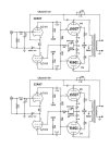
I threw together a first pass schematic, if you want to build to the Dave Gillespie 8800 type design with the excellent floating paraphase front end. Sorry it took a bit- between a bad cold and taxes, it's been a fun week.
The power supply schematic below includes the blue/blue filament winding for primary bucking (polarity not indicated but chosen for lowest filament voltages) and hum balance pots replaced with fixed resistors and connected to the 6V6GT cathodes.
For the main channels, I kept the tube numbering the same. This re-uses the existing "V3" 12AX7 as the left and right phase inverter, and adds the new "V1" 12AX7 that will be the left and right voltage amplifier. I have assigned tube numbers based upon your photo-shopped schematic, and pin numbers for each tube should be the most convenient to build. The original cathode resistors of the 6V6GT tubes seemed a little low to me (at 200 ohms) so I have tentatively bumped them up to 220 ohms to be cautious until you have actual voltage numbers and we can make any fine tune adjustments. If you want to run it with the original 200 ohm resistors it's probably fine, I just tend to be a little cautious at first.
The 1.3K feedback resistors should be good for a first start regardless of which transformer (new 8 ohm or existing 4 ohm) and when you get it going we can adjust that based upon the sensitivity of the amp. The "TBD" feedback "phase advance" or "frequency compensation" cap across the 1.3K feedback resistor will need to be selected based upon some scope pictures you will take when driving a very low amplitude 10khz square wave. Dave G found this value needs to be around ~750pF for two different tested transformers.
This is all just spaghetti to throw at the wall, and I probably biffed something somewhere. (cold medicine- yeah, that's it.) Chew on it, ask questions, request any change you like, and if you want to go in a different direction I can most likely draw that up too. This stuff is quick and fun to do on Paint.NET.